
SAACKE RSE-P PCB Board
SAACKE GmbH
New product
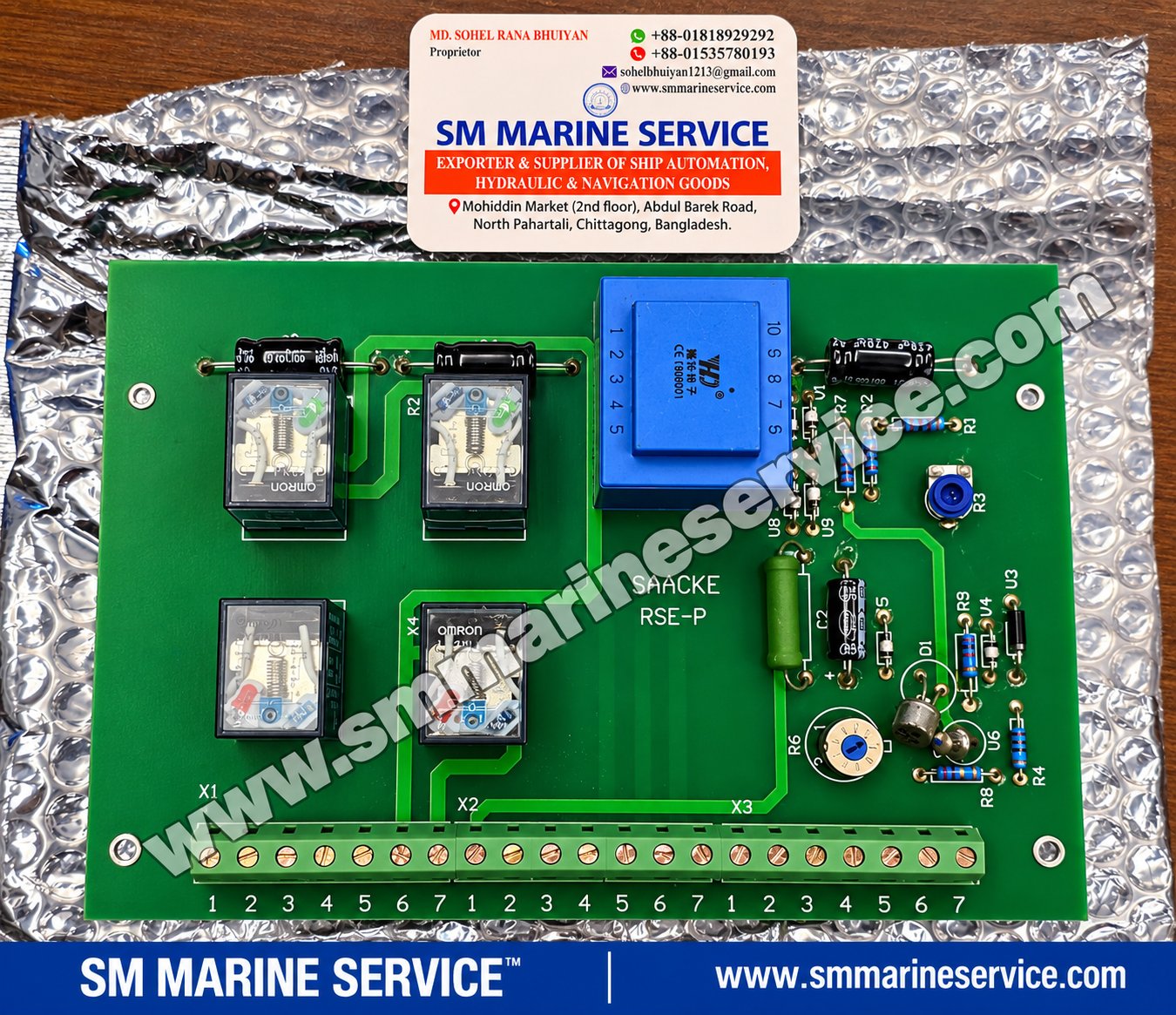
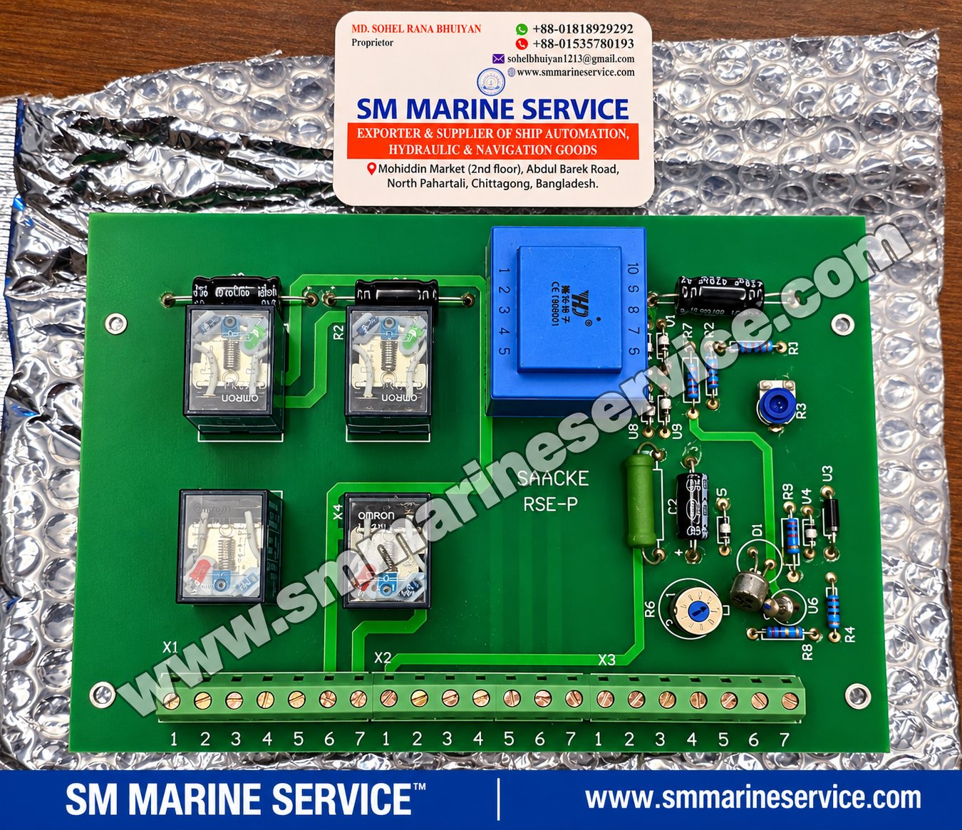
The SAACKE RSE-P PCB Board is an electronic circuit board identified by the marking SAACKE RSE-P, associated with marine boiler burner control applications.
The photographed board contains four plug-in OMRON relays, a blue enclosed transformer, adjustable electronic components and three terminal connection groups identified as X1, X2 and X3. These components suggest a board designed to interface electrical control signals and relay circuits within a larger burner or boiler control system.
SAACKE is a recognized German manufacturer of combustion technology and marine boiler burner systems. Its equipment is used in applications where controlled fuel combustion, reliable ignition sequences and combustion safety are essential.
For marine engineers and purchasing departments maintaining SAACKE installations, identifying the correct PCB is particularly important because the board's voltage rating, terminal connections, relay configuration and control logic must match the original system.
SM MARINE SERVICE™ supports international sourcing enquiries for SAACKE boiler burner PCB cards, controllers, flame-monitoring components and related marine automation spare parts through www.smmarineservice.com.
Original Product Photograph
Insert the supplied SM MARINE SERVICE™ full-board photograph here, retaining the genuine SAACKE RSE-P marking and the existing company watermark.
Suggested filename: saacke-rse-p-marine-boiler-burner-pcb-sm-marine-service.jpgALT: SAACKE RSE-P marine boiler burner PCB with OMRON relays, transformer and X1 X2 X3 terminals|
Parameter |
Details |
|---|---|
|
Manufacturer / Board Marking |
SAACKE |
|
Product |
Marine Boiler Burner Control PCB |
|
Exact PCB Marking |
RSE-P |
|
Alternative Search Names |
RSE P, RSEP |
|
Equipment Category |
Burner / Boiler Control Electronics |
|
Typical Application |
Marine boiler burner control panel |
|
Relay Components |
Four OMRON plug-in relays |
|
Transformer |
One blue enclosed transformer |
|
Adjustment Components |
R3 and R6 |
|
Terminal Groups |
X1, X2, X3 |
|
Terminals per Group |
Seven |
|
Total Screw Terminal Positions |
21 |
|
Supply Voltage |
Not verified from the photograph |
|
Market-Referenced Voltage |
220–230 V AC, 50/60 Hz — confirmation required |
|
Board Assembly Number |
Not clearly visible |
|
Serial Number |
Not clearly visible |
|
PCB Revision |
Not clearly visible |
|
Country of Board Manufacture |
Not verified |
|
Condition |
Not independently verified |
|
Exact Burner Compatibility |
Requires confirmation |
Identification note: The PCB itself clearly displays SAACKE RSE-P. However, the supplied photograph does not show a nameplate confirming 220 V, 230 V or 50/60 Hz. These voltage descriptions are therefore treated as market identification terms, not verified electrical ratings for this specific board.
The SAACKE RSE-P is a printed circuit board used in the context of marine boiler burner control equipment.
A burner control system typically consists of multiple interconnected components, including control relays, timers, flame supervision equipment, fuel valve circuits, ignition equipment, pressure switches and safety interlocks.
Within such systems, electronic relay boards can perform signal interfacing, control-voltage distribution or relay switching functions.
The photographed RSE-P board includes a transformer, rectification and electronic components, four relays and terminal blocks. This arrangement is consistent with a power-supply and relay-interface function.
However, the exact internal logic and safety role of this specific board cannot be established from its component layout alone.
The RSE-P should therefore be regarded as a SAACKE burner control PCB requiring application-specific identification, rather than a universally interchangeable burner controller.
Four transparent-cover OMRON relays are visible on the left side of the PCB.
These relays provide electrically operated switching contacts. Depending on the actual circuit design, they may be used to switch control signals or interface with external devices.
The exact coil voltage, contact rating and switching functions must be checked from the individual relay labels and circuit drawing.
A large blue transformer is mounted in the upper central section.
The transformer is likely associated with the board's internal electrical supply arrangement.
Its exact primary and secondary voltages have not been confirmed.
The lower edge of the PCB contains three screw-terminal groups:
X1: terminals 1–7
X2: terminals 1–7
X3: terminals 1–7
These provide the electrical connection points between the PCB and the surrounding control panel.
The terminal groups must not be wired by assumption. Their functions should be established from the approved SAACKE electrical schematic.
Two adjustable components are identifiable on the board:
R3: A blue trimmer in the upper-right component area.
R6: A circular adjustment component near the lower-right area.
Their actual functions and adjustment ranges are not confirmed. They should not be altered without the applicable service procedure.
The right side contains resistors, diodes, capacitors and semiconductor components.
These may support power conditioning, signal processing, timing or relay-driving circuits, depending on the board design.
The long screw-terminal strip provides serviceable electrical connections.
This arrangement can be important during replacement, but wire positions must be documented before any disconnection.
|
Specification |
Details |
|---|---|
|
PCB identification |
SAACKE RSE-P |
|
Board construction |
Component-populated printed circuit board |
|
Relay count |
Four |
|
Relay manufacturer |
OMRON |
|
Transformer count |
One |
|
Main terminal groups |
X1, X2, X3 |
|
Terminal positions |
7 per group |
|
Adjustable components |
R3 and R6 |
|
Passive components |
Resistors, capacitors, diodes |
|
Supply voltage |
Not confirmed |
|
Supply frequency |
Not confirmed |
|
Relay coil voltage |
Not confirmed |
|
Output contact ratings |
Not confirmed |
|
Dimensions |
Not measured |
|
Weight |
Not measured |
|
Exact control functions |
Not confirmed |
|
Applicable burner models |
Not confirmed |
The technical details above describe the photographed assembly. They should not be interpreted as a complete electrical specification or wiring instruction.
The RSE-P PCB is the primary product featured in this article. The following additional SAACKE references are useful for marine burner spare-parts sourcing, but they should not be interpreted as confirmed components of the photographed RSE-P board.
The RSE-P II is a related SAACKE control product reference.
Market descriptions include 24 V DC and wide-range AC-powered configurations, including the reference DDCC-M010502.
The RSE-P II should not be assumed to replace an RSE-P PCB directly. Electrical design, controller function, wiring and application compatibility require verification.
The RSE-1C is another SAACKE PCB reference relevant to burner control spare-parts enquiries.
Its relationship to a particular boiler installation must be confirmed through the original equipment documentation.
The BAC 2000 is a separate burner-control product family. Market references include a T10 configuration.
Buyers should provide the complete BAC 2000 identification and installed burner type when requesting replacement equipment.
These references are associated with burner-control equipment and should be identified individually before procurement.
They are not confirmed replacements for the RSE-P board.
Searchable references include:
FLUS 03 / FLUS03 / 1-8820-143105
The reference CE-0085AR0248 is also associated with market descriptions of this equipment.
Its precise configuration and suitability for a particular burner system require confirmation.
|
Reference |
Equipment / Identification |
|---|---|
|
4-8475-143146 |
SAACKE PCB card; Rev. 1.2 referenced |
|
4-8475-143147 |
SAACKE PCB card |
|
5-9975-108220 |
SAACKE PCB reference |
|
SSBm010301 |
H. SAACKE PCB reference |
|
OPTOIO-32 |
I/O module reference |
|
CMFS-1 |
Burner-control equipment reference |
|
IMS |
Integrated Management System reference |
These are related sourcing references supplied for this article. Their exact technical specifications and interchangeability have not been independently verified.
Other components relevant to marine burner maintenance enquiries include:
|
Component |
Reference |
|---|---|
|
Flame scanner / sensor |
FLS09 UV-5 |
|
Transformer |
B 9806173 |
|
Pressure switch |
DSB146F913 |
|
Other burner components |
Ignition transformers, servo motors, fuel valves and flame detectors |
Each component should be matched to the original burner manufacturer's specifications.
For enquiries covering these SAACKE equipment families, visit www.smmarineservice.com.
Auxiliary boilers generate steam for various shipboard services. Their burner-control equipment must operate with the appropriate fuel, combustion-air and safety systems.
SAACKE electronic control boards may be installed within associated burner-control cabinets, depending on the boiler and burner configuration.
Composite boilers may use exhaust-gas heat and oil-fired burner arrangements. Where SAACKE burner equipment is installed, the control system may contain specialized electronic cards and relay modules.
Burner control installations use coordinated electrical and electronic components to manage operating sequences and safety-related conditions.
The exact role of the RSE-P board within such a system must be established from the original circuit design.
When an existing control PCB fails, vessel operators may seek an identical replacement to avoid unnecessary changes to the installed wiring and control system.
Replacement selection should account for the board revision, electrical ratings and original burner configuration.
Additional Original Product Image
Use a close-up cropped from the supplied SM MARINE SERVICE™ photograph, focusing on the SAACKE RSE-P marking, blue transformer and right-side electronic components. Preserve all original markings.
Suggested filename: saacke-rse-p-pcb-transformer-electronic-components.jpgALT: SAACKE RSE-P burner control PCB transformer, capacitors, diodes and adjustment componentsA malfunction in a marine boiler burner control panel can arise from the PCB, external wiring, power supply, sensors or other associated control equipment.
The following are possible diagnostic considerations, not confirmed faults of the photographed unit.
Potential causes include missing control voltage, open safety interlocks, faulty relay contacts, a damaged electronic board or an unrelated burner-management fault.
The approved burner fault-finding procedure should be followed before replacing the PCB.
A loss of control power may be associated with supply protection, wiring, the transformer or internal power-conditioning components.
Qualified technicians should verify the incoming supply and the applicable circuit diagram.
A relay may fail because of a defective coil, damaged contact, incorrect control signal or faulty relay-driving circuit.
The relay type and ratings must be confirmed before replacement.
Possible contributors include loose terminals, vibration-related connections, deteriorated solder joints or unstable control voltage.
These issues should be investigated with the burner safely isolated and the relevant procedures followed.
Visible discoloration, overheating or damaged electronic components can indicate a problem.
Replacing an individual component without identifying the underlying electrical fault may lead to repeated failure.
The functions of R3 and R6 have not been verified. Uncontrolled adjustment could change the board's behavior.
Their settings should be preserved unless an approved manufacturer procedure specifically requires adjustment.
A burner-management system is safety-critical because it controls or supervises equipment associated with fuel combustion.
The RSE-P photograph does not establish whether this particular board performs flame supervision, ignition sequencing, safety shutdown or only auxiliary relay-interface functions.
Therefore, no specific SAACKE alarm codes, timing values or shutdown thresholds are claimed for this PCB.
Burner safety circuits, flame detection and fuel-valve interlocks must never be bypassed to test a suspected faulty board.
Only authorized personnel should diagnose or replace the PCB using the correct electrical documentation and lockout procedures.
For existing SAACKE burner-control installations, suitable maintenance considerations include inspection of PCB terminals, relay sockets, wiring, signs of overheating and moisture contamination.
The original terminal connections should be photographed and labeled before removing a board.
Any replacement relay should match the required coil voltage, contact ratings and mechanical configuration.
A board should not be energized using an assumed 220 V or 230 V supply simply because that voltage appears in a marketplace description.
Where applicable, burner commissioning and functional verification should be completed by qualified personnel after replacement.
SM MARINE SERVICE™ supports enquiries for a wide range of SAACKE marine boiler and burner control equipment, including the SAACKE RSE-P PCB and related control cards.
The supplied product information indicates a broad SAACKE spare-parts sourcing capability. Exact stock, condition, revision and testing status should be confirmed for each requested item.
Enquiries may include complete PCB assemblies, relay-interface cards, burner control units, flame-monitoring boards, ignition components, sensors and related electronic modules.
Customers can request quotations for new, used, refurbished or reconditioned equipment according to their requirements.
Please provide the following information:
Clear photograph of the original PCB, including the printed model and any rear-side markings
Original burner manufacturer and model
Boiler manufacturer and equipment identification
Supply voltage and frequency
Existing terminal wiring or approved connection diagram
Required quantity and preferred equipment condition
For the featured product, the main identification is SAACKE RSE-P, with the visible X1, X2 and X3 terminal arrangement and four OMRON relays.
Submit your enquiry to SM MARINE SERVICE™ at www.smmarineservice.com.
Ships frequently operate established boiler and burner installations for many years.
An existing control cabinet may rely on a specific PCB design, terminal arrangement and electrical interface.
Replacing a damaged board with a matching original assembly may reduce the need for modifications, provided that the replacement is correctly identified, inspected and tested.
The lifecycle status of the exact RSE-P board has not been independently confirmed, so it should not automatically be described as officially discontinued.
Where a newer controller generation is proposed, a qualified compatibility review is essential.
It is a PCB marked SAACKE RSE-P, associated with marine boiler burner control equipment.
Four OMRON relays, a transformer, electronic components, adjustable components and three screw-terminal groups are visible.
The supplied product information references 220–230 V, 50/60 Hz market descriptions. The exact supply rating is not confirmed from the photograph.
They are three terminal connection groups, each with seven screw-terminal positions.
They are adjustable components on the PCB. Their exact functions have not been verified.
Direct compatibility has not been confirmed. The electrical and functional requirements must be checked.
No. Compatibility depends on the original burner control system and board configuration.
Possible causes include control power loss, an open safety interlock, defective relay, sensor problem or another burner-control fault.
SM MARINE SERVICE™ accepts sourcing enquiries for a broad range of SAACKE boards and burner components. Specific availability requires confirmation.
Yes. Customers may request these conditions for sourcing review, subject to actual availability.
Send the PCB photograph, part number, burner model, boiler manufacturer, electrical rating and quantity.
Contact SM MARINE SERVICE™ through www.smmarineservice.com or info@smmarineservice.com.
The SAACKE RSE-P PCB Board is a marine boiler burner control circuit board featuring four OMRON plug-in relays, an enclosed transformer, electronic control components and three seven-position terminal groups marked X1, X2 and X3. The PCB is identified by the printed SAACKE RSE-P marking and is associated with marine burner-control applications. Its exact supply voltage and system compatibility require verification. SM MARINE SERVICE™ supports worldwide enquiries for SAACKE RSE-P replacement boards, related burner controllers, flame-monitoring components and marine boiler automation spare parts. Contact the company with the original PCB photograph and burner details for a quotation.
SM MARINE SERVICE™
Marine Automation & Navigation Equipment Supplier
Available Equipment Conditions:
New Equipment • Used Equipment • Refurbished Equipment • Reconditioned Equipment
Specific product condition and availability are subject to confirmation.
Stock Locations:
Bangladesh • China
Services:
Worldwide Shipping • Technical Support • Spare Parts Supply • Marine Equipment Sourcing
Contact Information
SM MARINE SERVICE™
Samir Market, DT Road, Pahartali, beside CDA Market, Chattogram, Bangladesh
Mobile / WhatsApp / Viber: +88 01818 929292
Email: info@smmarineservice.com
Website: https://www.smmarineservice.com/
For quotations on SAACKE RSE-P PCBs, RSE-P II controllers, FLUS 03 boards, BAC 2000 burner controls, flame sensors and other marine boiler burner spare parts, contact SM MARINE SERVICE™ with your equipment identification, photographs and technical requirements.
0

BDT 0

BDT 0

BDT 0

BDT 0
Marine Equipment Supplier