ESD5111 Engine Speed Control Unit
GAC Compatible / GAC-Type
New product
This creates a closed-loop engine speed regulation system.
Typical Electronic Governor Control Principle
Original simplified conceptual diagram. Actual installation and wiring depend on the engine and controller configuration.The SAACKE RSE-P PCB Board is an electronic circuit board identified by the marking SAACKE RSE-P, associated with marine boiler burner control applications.
The photographed board contains four plug-in OMRON relays, a blue enclosed transformer, adjustable electronic components and three terminal connection groups identified as X1, X2 and X3. These components suggest a board designed to interface electrical control signals and relay circuits within a larger burner or boiler control system.
SAACKE is a recognized German manufacturer of combustion technology and marine boiler burner systems. Its equipment is used in applications where controlled fuel combustion, reliable ignition sequences and combustion safety are essential.
For marine engineers and purchasing departments maintaining SAACKE installations, identifying the correct PCB is particularly important because the board's voltage rating, terminal connections, relay configuration and control logic must match the original system.
SM MARINE SERVICE™ supports international sourcing enquiries for SAACKE boiler burner PCB cards, controllers, flame-monitoring components and related marine automation spare parts through www.smmarineservice.com.
Original Product Photograph
Insert the supplied SM MARINE SERVICE™ full-board photograph here, retaining the genuine SAACKE RSE-P marking and the existing company watermark.
Suggested filename: saacke-rse-p-marine-boiler-burner-pcb-sm-marine-service.jpgALT: SAACKE RSE-P marine boiler burner PCB with OMRON relays, transformer and X1 X2 X3 terminals
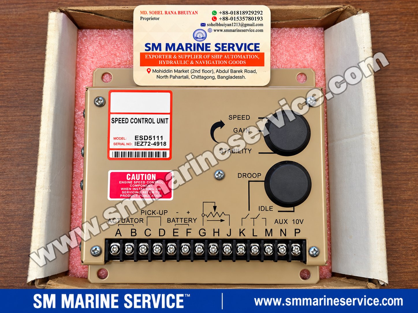
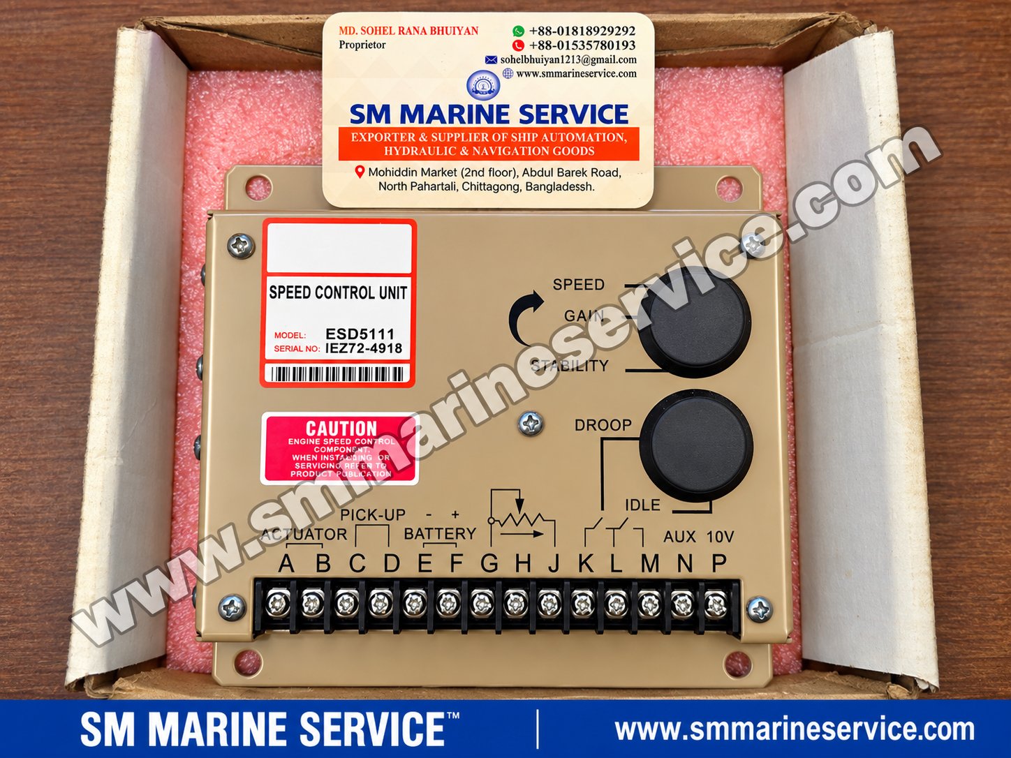
ESD5111 Engine Speed Control Unit – GAC-Type Electronic Governor Controller for Marine Diesel GeneratorsProduct IntroductionThe ESD5111 Engine Speed Control Unit is an electronic governor controller designed for engine-speed regulation in diesel generator and industrial engine applications. It belongs to the general ESD5100-style electronic speed control family, a design associated with Governors America Corp. (GAC) of the United States. The product photographed by SM MARINE SERVICE™ is marked ESD5111, with Serial No. IEZ72-4918. It has the familiar terminal layout and adjustment arrangement of a GAC-type electronic governor controller. An important identification distinction is that the photographed unit does not display a GAC manufacturer logo. It should therefore be described as a GAC-type or GAC-compatible ESD5111 controller, rather than represented as a verified genuine GAC-manufactured product. The unit is shown in its protective packaging and is described in the supplied product information as new in box. Its electrical testing status has not been independently established. For shipowners, generator service companies, marine engineers and purchasing managers, the ESD5111 is relevant when maintaining diesel engines fitted with electronic fuel-actuator speed regulation. SM MARINE SERVICE™ accepts enquiries for ESD5111 controllers, generator governor units, actuators, magnetic speed pickups and related marine automation spare parts through www.smmarineservice.com. Original SM MARINE SERVICE™ Product Photograph Use the supplied front-view photograph showing the ESD5111 model label, serial number, adjustment controls and complete terminal block. Retain the existing SM MARINE SERVICE™ watermark and genuine product markings. SEO filename: esd5111-gac-type-engine-speed-control-unit-sm-marine-service.jpgALT: ESD5111 GAC-type electronic engine speed control unit with governor adjustments and terminal connectionsProduct Information
What Is the ESD5111 Engine Speed Controller?The ESD5111 is an electronic device used to regulate the rotational speed of an engine. In a typical electronically governed diesel engine, the speed controller operates together with a magnetic pickup sensor and an electric fuel actuator. The magnetic pickup measures engine rotation through a signal generated by passing gear teeth. The controller compares the measured speed with its reference setting and adjusts the actuator command to increase or decrease fuel delivery. This creates a closed-loop engine speed regulation system. Typical Electronic Governor Control Principle Original simplified conceptual diagram. Actual installation and wiring depend on the engine and controller configuration.When the electrical load on a diesel generator changes, the engine experiences a corresponding change in mechanical demand. The speed controller responds by adjusting the fuel actuator to help maintain the target RPM. For a synchronous generator, stable engine RPM is essential because electrical frequency is directly related to rotational speed and generator pole count. The ESD5111 is not an Automatic Voltage Regulator (AVR). An AVR controls generator excitation and voltage, while the engine governor controls rotational speed and therefore helps regulate generator frequency. Main FeaturesElectronic Closed-Loop Speed RegulationThe controller continuously responds to speed feedback from the magnetic pickup and provides a command to the fuel actuator. Speed AdjustmentThe SPEED adjustment establishes the desired engine speed reference within the controller's operating range. Gain AdjustmentGAIN influences how strongly the controller responds to speed error. Improper gain adjustment can contribute to sluggish response or unstable operation. Stability AdjustmentSTABILITY influences the dynamic response of the governor system. It works with gain tuning to help achieve acceptable engine response without excessive oscillation. Droop FunctionDroop operation allows engine speed to decrease in a controlled relationship with increasing load. This operating characteristic may be used in certain generator load-sharing arrangements. Idle FunctionThe controller provides a terminal arrangement associated with idle-speed selection. Its use depends on the installed wiring and engine application. Remote Speed ReferenceExternal speed adjustment can be relevant to generator synchronizing and speed-control applications, subject to controller and system compatibility. Magnetic Pickup InputThe controller uses an engine-speed signal from a magnetic pickup sensor. Actuator OutputThe electronic output controls a compatible fuel actuator. Actuator electrical requirements must be checked before connecting a replacement controller. Additional Original Product Image Use a close-up of the original photograph showing the SPEED, GAIN, STABILITY, DROOP and IDLE adjustment areas. Do not redraw the labels or change their positions. SEO filename: esd5111-governor-speed-gain-stability-droop-adjustments.jpgALT: ESD5111 electronic governor speed gain stability droop and idle adjustment controlsMain Technical SpecificationsThe following technical data is based on the supplied ESD5111 product information and typical specifications associated with the ESD5111 controller design. Since the photographed unit does not show a verified OEM manufacturer name, these family-level specifications should be confirmed against the exact unit before installation.
Technical verification: These operating ranges have not been independently validated for the photographed GAC-type unit. A matching model number does not guarantee identical internal components, protection features or performance across manufacturers. Main Components & Terminal IdentificationThe ESD5111 front panel contains a clearly printed connection diagram. This is particularly useful for purchasing managers and technicians identifying the correct controller.
These terminal descriptions are identification information, not a substitute for the approved installation wiring diagram. Actuator Terminals A and BThe actuator output is used to drive a compatible electronic fuel-control actuator. A suitable actuator responds to the controller's electrical command by adjusting the engine's fuel-control mechanism. The actuator's voltage, current requirements, direction of operation and mechanical arrangement must match the application. Magnetic Pickup Terminals C and DThe magnetic pickup produces an electrical frequency signal corresponding to engine rotation. The controller uses this signal as speed feedback. An incorrectly installed pickup, damaged cable or inadequate signal may prevent proper speed regulation. Battery Supply Terminals E and FThe controller is associated with 12 V and 24 V DC engine electrical systems. Correct polarity and supply voltage are essential. The photographed terminal diagram identifies the negative and positive connections. External Speed Trim Terminals G, H and JThese terminals are associated with an external speed-setting potentiometer. Such arrangements can allow speed adjustment from a separate control location, depending on the installed system. Droop Selection Terminals K and LThe printed diagram identifies a droop-selection circuit. Droop settings are relevant where the governing strategy requires a speed-versus-load characteristic. Idle Selection Terminals L and MThese terminals are associated with idle-speed selection. Actual idle operation and speed settings depend on the controller configuration. Auxiliary Input NThe AUX terminal may be associated with external control equipment such as a synchronizer or load-sharing interface. Compatibility with external signals must be verified. Accessory Reference Terminal PThe front marking identifies an auxiliary 10 V reference. The permitted accessory current and electrical configuration should be checked before connection. Original Terminal Identification Image Insert a close-up from the SM MARINE SERVICE™ photograph covering the terminal strip A–P, battery polarity markings, actuator symbol, magnetic pickup symbol and AUX 10V marking. SEO filename: esd5111-governor-controller-terminal-a-to-p-wiring-identification.jpgALT: ESD5111 governor controller terminal identification for actuator magnetic pickup battery droop idle and auxiliary inputRelated GAC-Type Speed Controllers & Associated PartsThe following are related model references commonly encountered in electronic governor spare-parts enquiries. They are not automatically interchangeable with the photographed ESD5111.
ESD5111 and ESD5111TThe ESD5111T is associated with temperature-compensated controller designs. A replacement decision should be based on the exact manufacturer documentation, terminal arrangement and application requirements. ESD5111 and ESD5500EBoth names appear in electronic governor applications, but their control capabilities and electrical configurations should not be assumed identical. A change between these models may require technical assessment and adjustment. Electronic ActuatorsGAC-type systems may employ compatible electronic actuators to control engine fuel delivery. Actuator selection must consider mechanical mounting, fuel linkage, required force, travel and electrical characteristics. Magnetic Pickup SensorsMagnetic pickup sensors are important because the speed controller depends on reliable rotational feedback. A sensor with the wrong mechanical dimensions, electrical output or installation clearance may cause problems even when the controller is functioning correctly. For enquiries about ESD5111 controllers, related electronic actuators and magnetic pickups, visit www.smmarineservice.com. Marine & Industrial ApplicationsMarine Auxiliary Diesel GeneratorsAuxiliary generators supply electrical power for a ship's operational equipment. Electronic speed regulation helps maintain stable generator frequency as electrical demand changes. Emergency Diesel GeneratorsWhere the engine and control system are designed for an ESD5111-type governor, the controller may be used in emergency generator applications. Any replacement must comply with the vessel's approved equipment arrangement and operational requirements. Industrial Diesel Generator SetsESD5111-style controllers are also relevant to industrial generator installations using electronic fuel actuators and magnetic speed feedback. Diesel Engine Pump DrivesSome diesel-driven pump installations use electronic governors where controlled operating speed is required. Compressor and Industrial Engine ApplicationsElectronic speed controllers can be used with compatible engines powering compressors and industrial machinery. Generator Synchronizing & Load SharingIn appropriate installations, external speed-reference signals and droop functions can support generator synchronizing or load-sharing arrangements. The ESD5111 itself should not be described as a complete synchronizer or load-sharing controller. Common Problems & TroubleshootingEngine Hunting or Unstable RPMEngine hunting refers to repeated oscillation above and below the desired speed. Potential causes include incorrect governor tuning, mechanical fuel-linkage problems, unstable magnetic pickup signals, actuator issues or fluctuating engine load. An unstable engine does not automatically indicate a defective speed controller. Generator Frequency FluctuationIf engine speed varies, the output frequency of a synchronous generator can also vary. Check the engine's actual RPM, fuel system, governor feedback and connected load conditions. Engine Does Not Reach Rated SpeedPossible causes include incorrect speed reference, insufficient fuel delivery, actuator travel limitations, mechanical restrictions or controller configuration. No Actuator ResponsePossible causes include loss of controller power, missing speed feedback, incorrect wiring, actuator failure or an internal controller fault. Engine OverspeedOverspeed is a serious machinery hazard. An independent, correctly functioning overspeed protection system is essential. The electronic speed controller must not be relied upon as the sole overspeed safety device. Unstable Operation After Controller ReplacementA replacement may have different adjustment settings, control response or internal characteristics. Even when the terminal layout appears identical, compatibility and safe commissioning must be verified. Incorrect Magnetic Pickup SignalA damaged pickup cable, poor sensor installation or inadequate signal can interfere with speed feedback. Testing should follow the engine and controller manufacturer's procedures. Safety notice: Incorrect governor settings or wiring can cause unintended engine acceleration, loss of speed control or machinery damage. Installation, adjustment and commissioning should be performed only by qualified personnel using the applicable engine and governor documentation. Maintenance TipsRoutine maintenance of an electronic governor system should include inspection of electrical terminals, cable condition, magnetic pickup installation, actuator linkage and protective mounting. Check for loose connections, corrosion, damaged insulation and evidence of excessive heat. Before replacing a controller, record the original adjustment positions and identify the installed actuator and speed sensor. Any controller replacement should be followed by appropriate engine-speed verification, stability checks and confirmation that the independent shutdown and protection systems remain operational. Avoid adjusting SPEED, GAIN, STABILITY or DROOP without an approved commissioning procedure. Spare Parts & Replacement AvailabilitySM MARINE SERVICE™ supplies and sources marine automation equipment, electronic governor controllers, generator control components and engine spare parts for international customers. The featured ESD5111 GAC-type Engine Speed Control Unit is described in the supplied product information as new in box. Current stock quantity, electrical test status and delivery arrangements should be confirmed when requesting a quotation. Customers may enquire about:
New, used, refurbished and reconditioned equipment may be requested according to the customer's requirements, subject to availability. Information Required for a QuotationFor accurate matching, please send the controller model, photographs of the existing unit, engine manufacturer and model, 12 V or 24 V electrical system information, actuator model and required quantity. For the photographed unit, the principal identification is: Model: ESD5111 — Serial No.: IEZ72-4918 — GAC-type electronic engine speed controller. Contact SM MARINE SERVICE™ at www.smmarineservice.com for quotation and sourcing enquiries. Why ESD5111-Type Electronic Governors Are Still UsedMany marine and industrial diesel engines continue to operate with established electronic governor arrangements. When an engine is fitted with a particular actuator, magnetic pickup and speed-controller configuration, sourcing a suitable replacement controller can be preferable to redesigning the entire governor system. The ESD5111-style controller remains relevant to maintenance teams because its speed adjustment, droop selection and actuator-control arrangement are familiar in numerous generator applications. However, a controller carrying the same model designation is not necessarily electrically or mechanically identical across different manufacturers. For reliable operation, buyers should verify the replacement's electrical characteristics, actuator compatibility and approved engine settings. Frequently Asked Questions (FAQ)What is the ESD5111 speed control unit?It is an electronic engine governor controller used to regulate diesel engine speed through a magnetic pickup and compatible fuel actuator. Is the photographed ESD5111 a genuine GAC product?The unit follows a GAC-type design, but the photographed label does not show a GAC manufacturer logo. Genuine GAC manufacture has not been verified. What is the serial number of the photographed unit?The label shows IEZ72-4918. Is the ESD5111 an AVR?No. The ESD5111 controls engine speed, whereas an AVR regulates generator voltage. Does the ESD5111 work with 12 V and 24 V systems?The referenced ESD5111 controller family is associated with both supply systems. The exact unit's rating must be verified before installation. What are terminals A and B used for?They are identified as the actuator connection terminals. What are terminals C and D used for?They are identified as the magnetic pickup speed-sensor terminals. What causes engine hunting with an ESD5111 governor?Possible causes include governor tuning, unstable speed feedback, actuator issues, mechanical fuel-system problems or fluctuating loads. Can an ESD5500E replace an ESD5111?Compatibility cannot be assumed. The electrical design, actuator requirements and engine application must be reviewed. Can the ESD5111 be used for marine generators?It may be suitable for marine diesel generator applications designed around a compatible electronic governor system. Is the photographed ESD5111 new?The supplied product information identifies it as new in box. Electrical testing and current availability require confirmation. Where can I buy an ESD5111 governor controller?Contact SM MARINE SERVICE™ through www.smmarineservice.com with your model, voltage and engine details. Short Product DescriptionThe ESD5111 Engine Speed Control Unit is a GAC-type electronic governor controller designed for diesel engine and generator speed regulation. It works with a compatible magnetic pickup sensor and electric fuel actuator to help maintain engine RPM under changing operating conditions. The controller features SPEED, GAIN, STABILITY, DROOP and IDLE adjustment functions, together with a 14-terminal connection arrangement. The photographed unit is identified as Model ESD5111, Serial No. IEZ72-4918, and is described as new in box. SM MARINE SERVICE™ accepts worldwide enquiries for ESD5111 controllers, related electronic governors, actuators and marine generator spare parts. SM MARINE SERVICE™ — Company & Contact DetailsSM MARINE SERVICE™ Available Equipment Conditions: Specific product condition and availability are subject to confirmation. Stock Locations: Services: Contact Information SM MARINE SERVICE™ Mobile / WhatsApp / Viber: +88 01818 929292 For quotations on ESD5111 Engine Speed Control Units, GAC-type electronic governors, diesel generator actuators, magnetic pickups, generator control panels and other marine automation spare parts, contact SM MARINE SERVICE™ with your equipment model, photographs and technical requirements. |
|||||||||||||||||||||||||||||||||||||||||||||||||||||||||||||||||||||||||||||||||||||||||||||||||||||||||||||||||||||||||||
|---|---|---|---|---|---|---|---|---|---|---|---|---|---|---|---|---|---|---|---|---|---|---|---|---|---|---|---|---|---|---|---|---|---|---|---|---|---|---|---|---|---|---|---|---|---|---|---|---|---|---|---|---|---|---|---|---|---|---|---|---|---|---|---|---|---|---|---|---|---|---|---|---|---|---|---|---|---|---|---|---|---|---|---|---|---|---|---|---|---|---|---|---|---|---|---|---|---|---|---|---|---|---|---|---|---|---|---|---|---|---|---|---|---|---|---|---|---|---|---|---|---|---|---|
Identification note: The PCB itself clearly displays SAACKE RSE-P. However, the supplied photograph does not show a nameplate confirming 220 V, 230 V or 50/60 Hz. These voltage descriptions are therefore treated as market identification terms, not verified electrical ratings for this specific board.
The SAACKE RSE-P is a printed circuit board used in the context of marine boiler burner control equipment.
A burner control system typically consists of multiple interconnected components, including control relays, timers, flame supervision equipment, fuel valve circuits, ignition equipment, pressure switches and safety interlocks.
Within such systems, electronic relay boards can perform signal interfacing, control-voltage distribution or relay switching functions.
The photographed RSE-P board includes a transformer, rectification and electronic components, four relays and terminal blocks. This arrangement is consistent with a power-supply and relay-interface function.
However, the exact internal logic and safety role of this specific board cannot be established from its component layout alone.
The RSE-P should therefore be regarded as a SAACKE burner control PCB requiring application-specific identification, rather than a universally interchangeable burner controller.
Four transparent-cover OMRON relays are visible on the left side of the PCB.
These relays provide electrically operated switching contacts. Depending on the actual circuit design, they may be used to switch control signals or interface with external devices.
The exact coil voltage, contact rating and switching functions must be checked from the individual relay labels and circuit drawing.
A large blue transformer is mounted in the upper central section.
The transformer is likely associated with the board's internal electrical supply arrangement.
Its exact primary and secondary voltages have not been confirmed.
The lower edge of the PCB contains three screw-terminal groups:
X1: terminals 1–7
X2: terminals 1–7
X3: terminals 1–7
These provide the electrical connection points between the PCB and the surrounding control panel.
The terminal groups must not be wired by assumption. Their functions should be established from the approved SAACKE electrical schematic.
Two adjustable components are identifiable on the board:
R3: A blue trimmer in the upper-right component area.
R6: A circular adjustment component near the lower-right area.
Their actual functions and adjustment ranges are not confirmed. They should not be altered without the applicable service procedure.
The right side contains resistors, diodes, capacitors and semiconductor components.
These may support power conditioning, signal processing, timing or relay-driving circuits, depending on the board design.
The long screw-terminal strip provides serviceable electrical connections.
This arrangement can be important during replacement, but wire positions must be documented before any disconnection.
|
Specification |
Details |
|---|---|
|
PCB identification |
SAACKE RSE-P |
|
Board construction |
Component-populated printed circuit board |
|
Relay count |
Four |
|
Relay manufacturer |
OMRON |
|
Transformer count |
One |
|
Main terminal groups |
X1, X2, X3 |
|
Terminal positions |
7 per group |
|
Adjustable components |
R3 and R6 |
|
Passive components |
Resistors, capacitors, diodes |
|
Supply voltage |
Not confirmed |
|
Supply frequency |
Not confirmed |
|
Relay coil voltage |
Not confirmed |
|
Output contact ratings |
Not confirmed |
|
Dimensions |
Not measured |
|
Weight |
Not measured |
|
Exact control functions |
Not confirmed |
|
Applicable burner models |
Not confirmed |
The technical details above describe the photographed assembly. They should not be interpreted as a complete electrical specification or wiring instruction.
The RSE-P PCB is the primary product featured in this article. The following additional SAACKE references are useful for marine burner spare-parts sourcing, but they should not be interpreted as confirmed components of the photographed RSE-P board.
The RSE-P II is a related SAACKE control product reference.
Market descriptions include 24 V DC and wide-range AC-powered configurations, including the reference DDCC-M010502.
The RSE-P II should not be assumed to replace an RSE-P PCB directly. Electrical design, controller function, wiring and application compatibility require verification.
The RSE-1C is another SAACKE PCB reference relevant to burner control spare-parts enquiries.
Its relationship to a particular boiler installation must be confirmed through the original equipment documentation.
The BAC 2000 is a separate burner-control product family. Market references include a T10 configuration.
Buyers should provide the complete BAC 2000 identification and installed burner type when requesting replacement equipment.
These references are associated with burner-control equipment and should be identified individually before procurement.
They are not confirmed replacements for the RSE-P board.
Searchable references include:
FLUS 03 / FLUS03 / 1-8820-143105
The reference CE-0085AR0248 is also associated with market descriptions of this equipment.
Its precise configuration and suitability for a particular burner system require confirmation.
|
Reference |
Equipment / Identification |
|---|---|
|
4-8475-143146 |
SAACKE PCB card; Rev. 1.2 referenced |
|
4-8475-143147 |
SAACKE PCB card |
|
5-9975-108220 |
SAACKE PCB reference |
|
SSBm010301 |
H. SAACKE PCB reference |
|
OPTOIO-32 |
I/O module reference |
|
CMFS-1 |
Burner-control equipment reference |
|
IMS |
Integrated Management System reference |
These are related sourcing references supplied for this article. Their exact technical specifications and interchangeability have not been independently verified.
Other components relevant to marine burner maintenance enquiries include:
|
Component |
Reference |
|---|---|
|
Flame scanner / sensor |
FLS09 UV-5 |
|
Transformer |
B 9806173 |
|
Pressure switch |
DSB146F913 |
|
Other burner components |
Ignition transformers, servo motors, fuel valves and flame detectors |
Each component should be matched to the original burner manufacturer's specifications.
For enquiries covering these SAACKE equipment families, visit www.smmarineservice.com.
Auxiliary boilers generate steam for various shipboard services. Their burner-control equipment must operate with the appropriate fuel, combustion-air and safety systems.
SAACKE electronic control boards may be installed within associated burner-control cabinets, depending on the boiler and burner configuration.
Composite boilers may use exhaust-gas heat and oil-fired burner arrangements. Where SAACKE burner equipment is installed, the control system may contain specialized electronic cards and relay modules.
Burner control installations use coordinated electrical and electronic components to manage operating sequences and safety-related conditions.
The exact role of the RSE-P board within such a system must be established from the original circuit design.
When an existing control PCB fails, vessel operators may seek an identical replacement to avoid unnecessary changes to the installed wiring and control system.
Replacement selection should account for the board revision, electrical ratings and original burner configuration.
Additional Original Product Image
Use a close-up cropped from the supplied SM MARINE SERVICE™ photograph, focusing on the SAACKE RSE-P marking, blue transformer and right-side electronic components. Preserve all original markings.
Suggested filename: saacke-rse-p-pcb-transformer-electronic-components.jpgALT: SAACKE RSE-P burner control PCB transformer, capacitors, diodes and adjustment componentsA malfunction in a marine boiler burner control panel can arise from the PCB, external wiring, power supply, sensors or other associated control equipment.
The following are possible diagnostic considerations, not confirmed faults of the photographed unit.
Potential causes include missing control voltage, open safety interlocks, faulty relay contacts, a damaged electronic board or an unrelated burner-management fault.
The approved burner fault-finding procedure should be followed before replacing the PCB.
A loss of control power may be associated with supply protection, wiring, the transformer or internal power-conditioning components.
Qualified technicians should verify the incoming supply and the applicable circuit diagram.
A relay may fail because of a defective coil, damaged contact, incorrect control signal or faulty relay-driving circuit.
The relay type and ratings must be confirmed before replacement.
Possible contributors include loose terminals, vibration-related connections, deteriorated solder joints or unstable control voltage.
These issues should be investigated with the burner safely isolated and the relevant procedures followed.
Visible discoloration, overheating or damaged electronic components can indicate a problem.
Replacing an individual component without identifying the underlying electrical fault may lead to repeated failure.
The functions of R3 and R6 have not been verified. Uncontrolled adjustment could change the board's behavior.
Their settings should be preserved unless an approved manufacturer procedure specifically requires adjustment.
A burner-management system is safety-critical because it controls or supervises equipment associated with fuel combustion.
The RSE-P photograph does not establish whether this particular board performs flame supervision, ignition sequencing, safety shutdown or only auxiliary relay-interface functions.
Therefore, no specific SAACKE alarm codes, timing values or shutdown thresholds are claimed for this PCB.
Burner safety circuits, flame detection and fuel-valve interlocks must never be bypassed to test a suspected faulty board.
Only authorized personnel should diagnose or replace the PCB using the correct electrical documentation and lockout procedures.
For existing SAACKE burner-control installations, suitable maintenance considerations include inspection of PCB terminals, relay sockets, wiring, signs of overheating and moisture contamination.
The original terminal connections should be photographed and labeled before removing a board.
Any replacement relay should match the required coil voltage, contact ratings and mechanical configuration.
A board should not be energized using an assumed 220 V or 230 V supply simply because that voltage appears in a marketplace description.
Where applicable, burner commissioning and functional verification should be completed by qualified personnel after replacement.
SM MARINE SERVICE™ supports enquiries for a wide range of SAACKE marine boiler and burner control equipment, including the SAACKE RSE-P PCB and related control cards.
The supplied product information indicates a broad SAACKE spare-parts sourcing capability. Exact stock, condition, revision and testing status should be confirmed for each requested item.
Enquiries may include complete PCB assemblies, relay-interface cards, burner control units, flame-monitoring boards, ignition components, sensors and related electronic modules.
Customers can request quotations for new, used, refurbished or reconditioned equipment according to their requirements.
Please provide the following information:
Clear photograph of the original PCB, including the printed model and any rear-side markings
Original burner manufacturer and model
Boiler manufacturer and equipment identification
Supply voltage and frequency
Existing terminal wiring or approved connection diagram
Required quantity and preferred equipment condition
For the featured product, the main identification is SAACKE RSE-P, with the visible X1, X2 and X3 terminal arrangement and four OMRON relays.
Submit your enquiry to SM MARINE SERVICE™ at www.smmarineservice.com.
Ships frequently operate established boiler and burner installations for many years.
An existing control cabinet may rely on a specific PCB design, terminal arrangement and electrical interface.
Replacing a damaged board with a matching original assembly may reduce the need for modifications, provided that the replacement is correctly identified, inspected and tested.
The lifecycle status of the exact RSE-P board has not been independently confirmed, so it should not automatically be described as officially discontinued.
Where a newer controller generation is proposed, a qualified compatibility review is essential.
It is a PCB marked SAACKE RSE-P, associated with marine boiler burner control equipment.
Four OMRON relays, a transformer, electronic components, adjustable components and three screw-terminal groups are visible.
The supplied product information references 220–230 V, 50/60 Hz market descriptions. The exact supply rating is not confirmed from the photograph.
They are three terminal connection groups, each with seven screw-terminal positions.
They are adjustable components on the PCB. Their exact functions have not been verified.
Direct compatibility has not been confirmed. The electrical and functional requirements must be checked.
No. Compatibility depends on the original burner control system and board configuration.
Possible causes include control power loss, an open safety interlock, defective relay, sensor problem or another burner-control fault.
SM MARINE SERVICE™ accepts sourcing enquiries for a broad range of SAACKE boards and burner components. Specific availability requires confirmation.
Yes. Customers may request these conditions for sourcing review, subject to actual availability.
Send the PCB photograph, part number, burner model, boiler manufacturer, electrical rating and quantity.
Contact SM MARINE SERVICE™ through www.smmarineservice.com or info@smmarineservice.com.
The SAACKE RSE-P PCB Board is a marine boiler burner control circuit board featuring four OMRON plug-in relays, an enclosed transformer, electronic control components and three seven-position terminal groups marked X1, X2 and X3. The PCB is identified by the printed SAACKE RSE-P marking and is associated with marine burner-control applications. Its exact supply voltage and system compatibility require verification. SM MARINE SERVICE™ supports worldwide enquiries for SAACKE RSE-P replacement boards, related burner controllers, flame-monitoring components and marine boiler automation spare parts. Contact the company with the original PCB photograph and burner details for a quotation.
SM MARINE SERVICE™
Marine Automation & Navigation Equipment Supplier
Available Equipment Conditions:
New Equipment • Used Equipment • Refurbished Equipment • Reconditioned Equipment
Specific product condition and availability are subject to confirmation.
Stock Locations:
Bangladesh • China
Services:
Worldwide Shipping • Technical Support • Spare Parts Supply • Marine Equipment Sourcing
Contact Information
SM MARINE SERVICE™
Samir Market, DT Road, Pahartali, beside CDA Market, Chattogram, Bangladesh
Mobile / WhatsApp / Viber: +88 01818 929292
Email: info@smmarineservice.com
Website: https://www.smmarineservice.com/
For quotations on SAACKE RSE-P PCBs, RSE-P II controllers, FLUS 03 boards, BAC 2000 burner controls, flame sensors and other marine boiler burner spare parts, contact SM MARINE SERVICE™ with your equipment identification, photographs and technical requirements.
0

BDT 0

BDT 0

BDT 0

BDT 0
Marine Equipment Supplier