
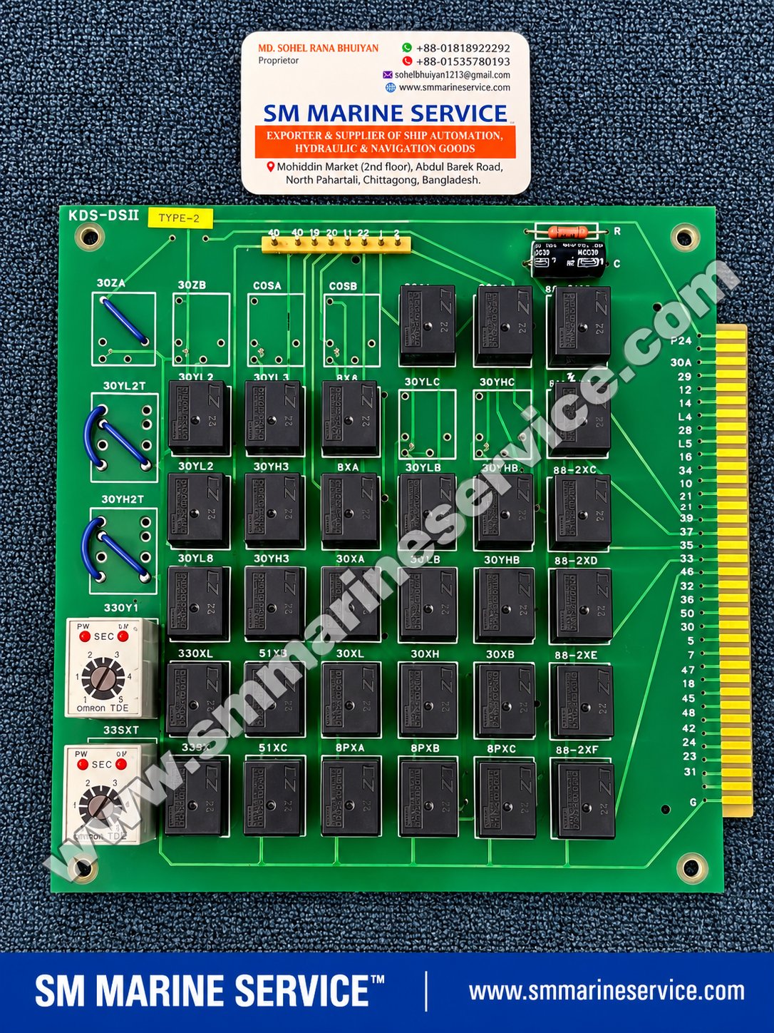
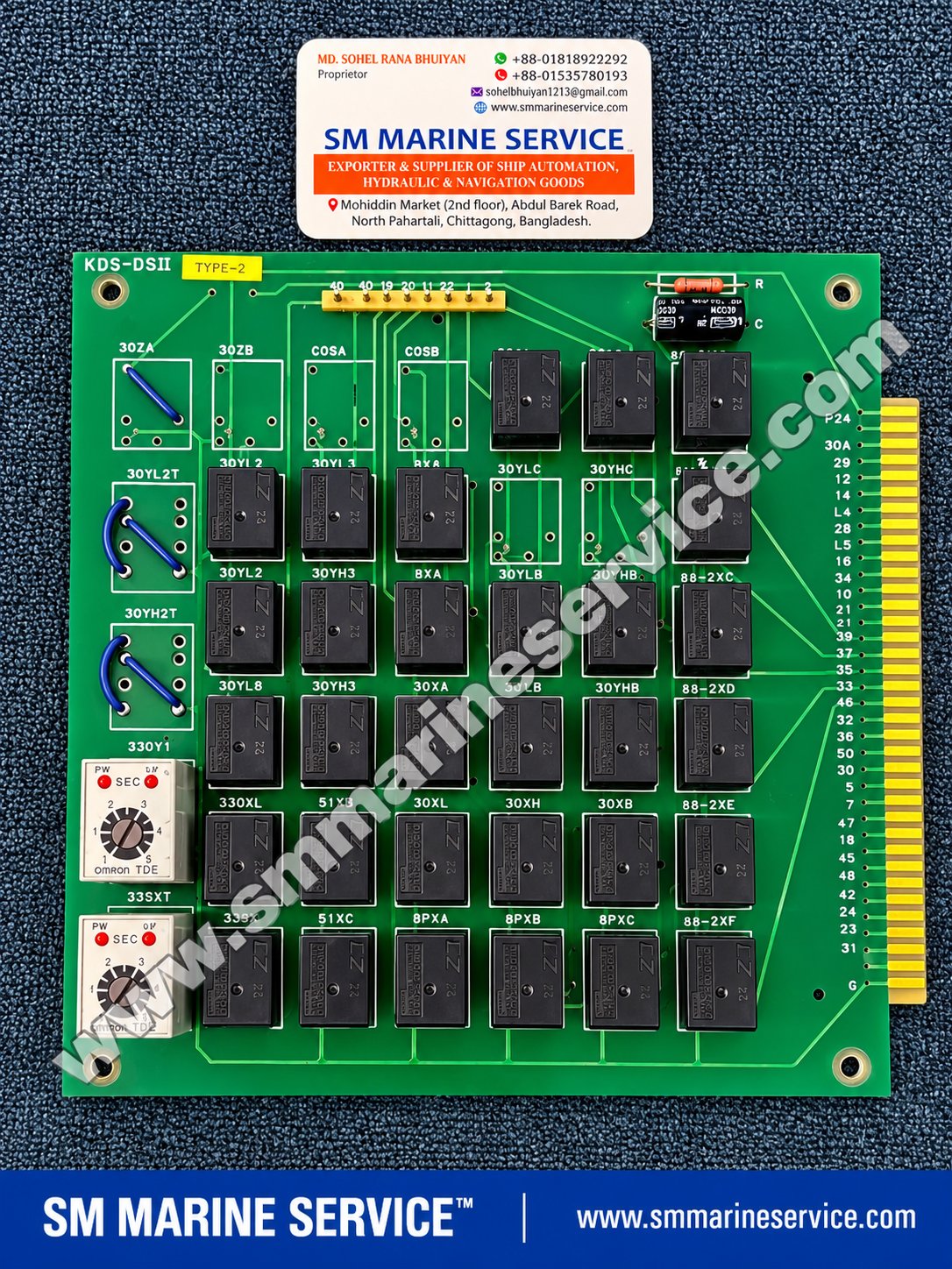
KDS-DSII TYPE-2 Marine Relay Sequence Control PCB Card
TDE OMRON Takamisawa-style relay components
New product
The KDS-DSII TYPE-2 is a plug-in relay logic printed circuit board featuring multiple electromechanical relays, two adjustable OMRON timing units, configurable jumper positions and a gold-contact edge connector.
The board is suitable for identification as a relay sequence control PCB of the type used in marine electrical and machinery control panels. Its exact original equipment application has not yet been confirmed.
Unlike a programmable logic controller, this style of board uses physical relay contacts and timing devices to implement predefined control sequences and electrical interlocks.
For vessels maintaining older control systems, obtaining a replacement card with the correct board identifier, type designation, component arrangement and jumper configuration is particularly important.
SM MARINE SERVICE™ supports international sourcing enquiries for legacy marine control PCBs and relay assemblies through www.smmarineservice.com.
|
Parameter |
Details |
|---|---|
|
Board Identification |
KDS-DSII |
|
Visible Type Sticker |
TYPE-2 |
|
Product Category |
Relay logic / sequence control PCB |
|
Manufacturer |
Not identified from photograph |
|
PCB Construction |
Component-populated printed circuit board |
|
Relay Technology |
Electromechanical relays |
|
Relay Brand Markings |
Takamisawa-style relay components; individual markings require close-up confirmation |
|
Timer Brand |
OMRON |
|
Timer Marking |
TDE |
|
Timer Quantity |
2 |
|
Timer Range |
Visible SEC scale, approximately 0–5 seconds |
|
Connector |
Multi-contact edge connector |
|
Power Terminal Marking |
P24 and G |
|
Board Weight |
Approximately 520–530 g, supplied estimate |
|
Condition |
Used, original, as described |
|
Exact System Application |
Not verified |
|
Original Equipment Manufacturer |
Not verified |
Identification note: The actual photograph clearly shows a yellow TYPE-2 sticker. The supplied text also mentions TYPE-0, but that does not match this particular image. Buyers should quote KDS-DSII TYPE-2 when enquiring about the photographed card.
The KDS-DSII is a relay-based sequence control board designed to process discrete electrical conditions and operate relay outputs according to an established wiring arrangement.
Such cards are commonly associated with traditional marine automation systems where relay logic is used instead of, or alongside, programmable electronic control systems.
A relay sequence board may be used to implement functions such as start permissions, stop conditions, auxiliary contactor operation, changeover interlocks and status feedback.
However, the precise functions of the photographed KDS-DSII card cannot be confirmed without its schematic diagram or the model of the equipment in which it was installed.
The important distinction is that KDS-DSII is the visible board identifier, while TYPE-2 is the visible configuration/type marking.
A replacement with a different TYPE marking should not be assumed electrically interchangeable.
The board contains numerous black rectangular relay components arranged in rows.
These relays provide switching contacts for implementing hardwired control logic.
Depending on the circuit design, individual relays may handle permissive signals, status feedback, interlocks or control outputs.
The exact coil voltage, contact rating and pin arrangement must be verified from each relay's complete part number.
Two OMRON TDE timing units are fitted along the left side of the PCB.
Each timer has a front adjustment dial and visible status indicators marked PW and UP.
The timer face includes a SEC marking and an approximately 0–5-second adjustment scale.
These devices can introduce intentional time delays into a relay sequence, helping prevent unwanted simultaneous operation or allowing a defined interval between control events.
The actual timing behavior depends on the timer variant and circuit wiring.
Several PCB locations contain wire jumper links or unpopulated link positions.
Visible identifiers include:
30ZA, 30ZB, COSA, COSB, 30YL2T and 30YH2T.
These positions may be used to establish circuit options or variant-specific connections.
Their exact purpose must be established from the original circuit drawing.
Do not copy jumper positions from another board merely because it carries the same KDS-DSII marking.
The board has a long edge connector on the right side.
Visible markings include P24, G and multiple numbered or letter-numbered contacts.
The connector provides the interface between the PCB and its mating card slot or control-panel backplane.
Its condition is important because oxidation, physical damage or poor contact pressure can cause intermittent control failures.
A resistor and capacitor arrangement is visible near the top-right corner of the board.
Such components may be used for electrical noise or switching-transient suppression, depending on the actual circuit design.
The exact component ratings and function require confirmation from the schematic.
|
Specification |
Details |
|---|---|
|
Model |
KDS-DSII |
|
Type |
TYPE-2, as photographed |
|
Board Technology |
Electromechanical relay logic |
|
Timer Modules |
Two OMRON TDE units |
|
Timer Dial |
Approximately 0–5 seconds |
|
Relay Count |
Approximately 25–30 populated relay positions; exact count should be confirmed |
|
Relay Coil Rating |
Not independently verified |
|
Power Reference |
P24 and G markings |
|
Nominal Supply |
24 V DC is suggested by P24; requires schematic confirmation |
|
Connector |
Gold-contact edge connector |
|
Jumper Configuration |
Wire links and selectable positions |
|
Communications Interface |
No digital communications interface identified |
|
Dimensions |
Not measured |
|
Weight |
Approximately 520–530 g |
|
Manufacturing Origin |
Not verified |
|
Compatible Control Panel |
Not verified |
The P24 marking is consistent with a positive 24 V supply reference, but it does not independently establish the voltage rating of every circuit or relay on the board.
The principal replacement identifier is KDS-DSII TYPE-2. The board code and type marking should both be included on purchase enquiries.
Multiple black relays are installed across the PCB. Their markings appear consistent with a Takamisawa/Fujitsu-style relay family, but the precise complete relay part number is not sufficiently legible to confirm its coil voltage or contact specification.
The board contains two adjustable OMRON TDE timer assemblies. They are relevant to repair enquiries involving incorrect sequence timing, non-operation or intermittent control behavior.
The following markings are useful when identifying the board or discussing a particular component location:
|
Group |
Visible / Reported Markings |
|---|---|
|
Board |
KDS-DSII, TYPE-2 |
|
Jumper / configuration areas |
30ZA, 30ZB, COSA, COSB |
|
Upper relay positions |
30YL2, 30YH3, 8XR |
|
Other relay positions |
30YLB, 30YHB, 30XA, 30XB, 30XL, 30XH |
|
Additional control positions |
33XL, 33SX, 51XB, 51XC |
|
Auxiliary positions |
8PXA, 8PXB, 8PXC |
|
Contactor-related labels |
88-2XC, 88-2XD, 88-2XE, 88-2XF |
|
Timing positions |
33QXT, 33SXT |
|
Supply/contact markings |
P24, G and numbered edge contacts |
Some small silkscreen characters are partly obscured by components or watermark text. The original PCB should be checked before ordering an individual component.
Several markings resemble conventional electrical control-device designations.
For example, 51 is commonly associated with AC time-overcurrent protection, while 88 is associated with an auxiliary motor or motor-generator device under ANSI/IEEE device-number conventions.
However, the use of these numbers as prefixes in PCB relay labels does not prove that the corresponding relay performs the standard device function.
On the KDS-DSII, these are best treated as circuit position identifiers until the manufacturer's drawing confirms their actual roles.
The KDS-DSII belongs to a class of control boards suitable for relay sequencing and interlocking applications.
Potential equipment categories include marine electrical switchboards, auxiliary machinery control panels, generator control assemblies and engine-related automation panels.
Such applications can involve:
Starting and stopping sequences
Timed relay operations
Electrical permissive and interlock logic
Contactor control
Alarm and status relay circuits
Changeover or standby equipment sequencing
Application limitation: No reliable documentation was located that establishes the exact machinery or vessel system for which this particular KDS-DSII TYPE-2 card was manufactured. These are relevant relay-board applications, not confirmed installation claims.
Possible causes include an absent control signal, incorrect supply, damaged relay coil, poor connector contact or an upstream interlock condition.
Check the actual relay coil rating before applying test voltage.
Mechanical relay contacts may deteriorate after repeated switching, especially where loads or switching transients are significant.
Symptoms can include intermittent output, high contact resistance or failure to switch.
A failed relay, missing permissive input, defective timer or incorrect jumper configuration may interrupt the expected sequence.
Trace the control circuit using the original drawing rather than assuming a relay's function from its printed label.
Inspect the relevant timer's supply, adjustment setting, indicator condition and output behavior.
A timing fault may prevent a later relay from operating even when the preceding relay is healthy.
Inspect the edge connector for contamination, corrosion, worn contacts, loose seating or damage.
Repeated insertion and removal can also affect connector reliability.
Check that the replacement matches the original board code, TYPE designation, jumper links and component population.
An apparently identical PCB may implement a different control sequence.
Inspect for overheating, cracked solder joints, corrosion, damaged copper tracks and evidence of previous repair.
Board-level repair should be performed by qualified electronics technicians with the assembly isolated from power.
Inspect the PCB periodically during approved equipment maintenance. Pay particular attention to relay condition, timer modules, edge contacts, jumper links and solder joints.
Record the original timer settings and jumper arrangement before removing the board.
Do not clean gold contacts with aggressive abrasives or make undocumented changes to relay wiring.
For a safety-related control system, any replacement must undergo the vessel's prescribed functional and interlock checks before being returned to service.
SM MARINE SERVICE™ supports enquiries for the KDS-DSII TYPE-2 Relay Sequence Control PCB Card and related marine automation control-board components.
The photographed item is described as a used, original PCB. Its operating test results have not been provided, so tested-working status should be confirmed before quotation.
Depending on sourcing availability, customers may enquire about complete replacement boards, matching relay components, OMRON timer assemblies and other legacy marine control PCBs.
For replacement enquiries, please provide the exact board marking, yellow TYPE label, photographs of both PCB sides, relay and timer markings, equipment manufacturer, control-panel model and required quantity.
International customers can contact SM MARINE SERVICE™ for availability and quotation assistance.
Marine relay sequence cards often use similar mechanical layouts while differing in electrical logic.
A different jumper configuration, relay contact arrangement or edge-connector assignment may change the behavior of the control system.
For this reason, KDS-DSII TYPE-2 should be treated as the specific identification of the photographed card.
A KDS-DSII TYPE-0 or TYPE-1 board must not be treated as a confirmed direct substitute without documented compatibility.
Many existing marine and industrial control installations continue to use electromechanical relay logic because it is integrated into the original wiring and operating sequence.
Replacing a failed PCB with a correctly matched unit can help preserve the existing control arrangement without redesigning the entire system.
However, replacement must account for the original interlocks, equipment safety functions, relay timing and electrical interfaces.
It is a relay-based printed circuit board identified by the KDS-DSII marking and fitted with electromechanical relays and timing devices.
The yellow sticker clearly reads TYPE-2.
The original board manufacturer has not been verified from the available markings.
It is relevant to relay-based marine control applications, but a specific generator-control application has not been confirmed.
The board carries a P24 marking, suggesting a 24 V supply reference. The complete electrical rating requires confirmation.
Two OMRON TDE adjustable timing units are visible.
Individual relay replacement may be possible if the exact component specification, footprint and contact arrangement are matched.
Interchangeability has not been established. The original TYPE marking and configuration must be checked.
Possible causes include contact wear, timer failure, damaged PCB tracks, loose connections, corrosion and supply or external control faults.
You can enquire with SM MARINE SERVICE™ about used replacement boards. Availability and testing status require confirmation.
Provide the PCB code, TYPE marking, front and rear photographs, control-panel details and quantity.
Yes. The company handles international marine and industrial equipment sourcing enquiries, with product-specific supply and shipping arrangements confirmed during quotation.
The KDS-DSII TYPE-2 Relay Sequence Control PCB Card is a plug-in electronic control board fitted with multiple electromechanical relays, two OMRON TDE adjustable timers, jumper configuration positions and a gold-contact edge connector. It is relevant to relay logic and timed-sequence applications in marine electrical and industrial control systems. The photographed board is marked KDS-DSII with a yellow TYPE-2 identification sticker and is described as a used original unit. Its exact manufacturer, installed system and electrical specifications require confirmation. SM MARINE SERVICE™ supports worldwide enquiries for matching replacement PCBs and related marine automation spare parts.
SM MARINE SERVICE™
Marine Automation & Navigation Equipment Supplier
Available Equipment Conditions:
New Equipment • Used Equipment • Refurbished Equipment • Reconditioned Equipment
Specific product condition and availability are subject to confirmation.
Stock Locations:
Bangladesh • China
Services:
Worldwide Shipping • Technical Support • Spare Parts Supply • Marine Equipment Sourcing
Contact Information
SM MARINE SERVICE™
Samir Market, DT Road, Pahartali, beside CDA Market, Chattogram, Bangladesh
Mobile / WhatsApp / Viber: +88 01818 929292
Email: info@smmarineservice.com
Website: https://www.smmarineservice.com/
For KDS-DSII TYPE-2 PCB replacement enquiries, relay sequence control cards, OMRON timer assemblies and other marine automation spare parts, contact SM MARINE SERVICE™ with your equipment details and photographs for a suitable sourcing quotation.
0

BDT 0

BDT 0

BDT 0

BDT 0
Marine Equipment Supplier