
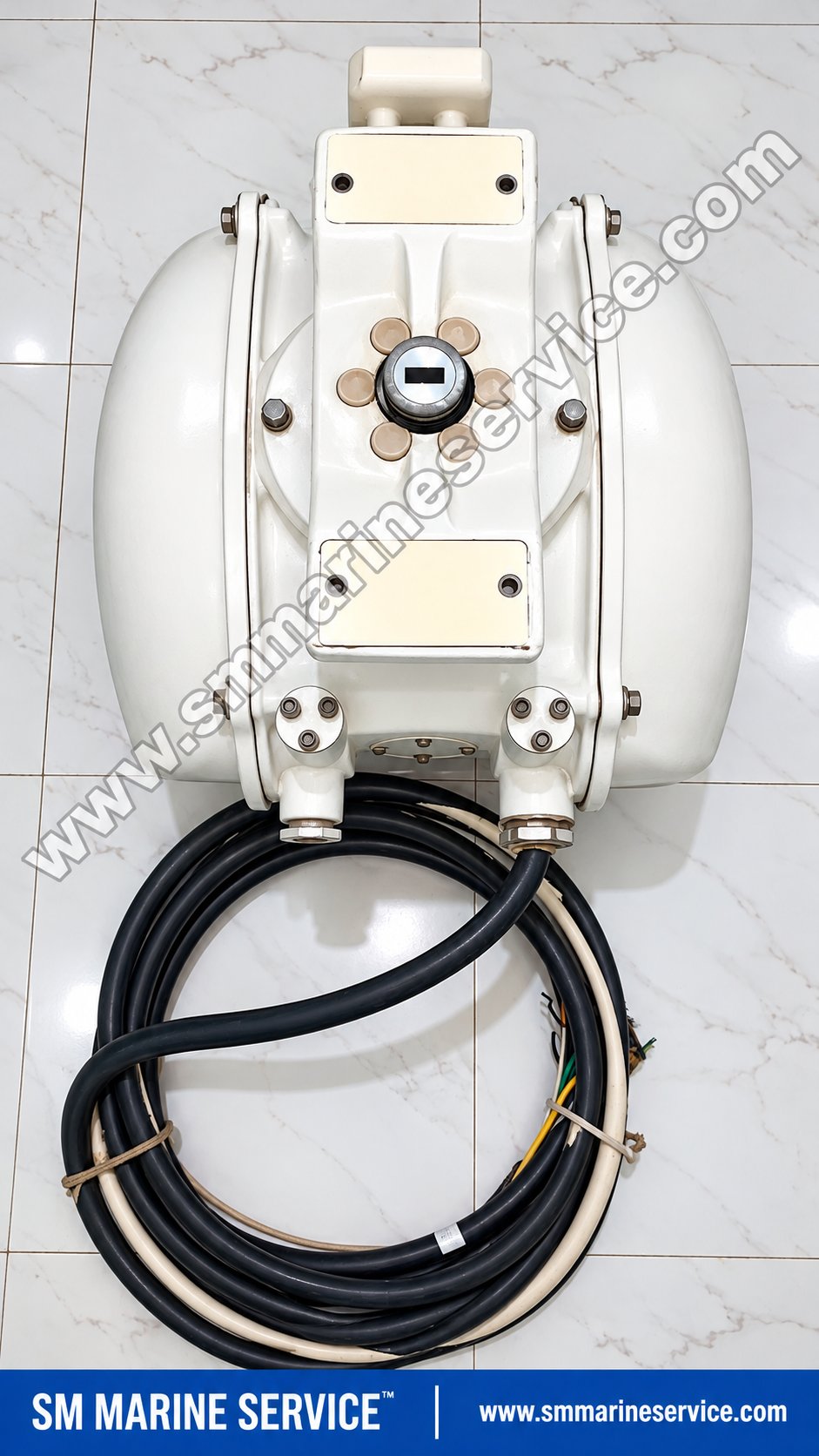
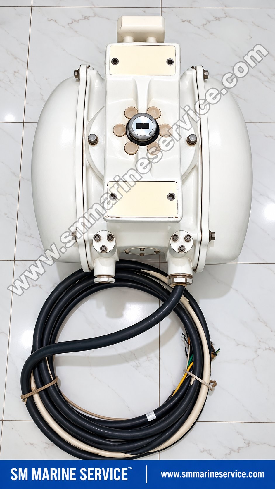
JRC NKE-1125-92 Radar Scanner 25kW
Japan Radio Co., Ltd. (JRC)
Refurbished
|
Specification |
Details |
|---|---|
|
Manufacturer |
Japan Radio Co., Ltd. (JRC) |
|
Country of Manufacture |
Japan, according to the nameplate |
|
Product Name |
Marine Radar Scanner Unit |
|
Exact Model |
NKE-1125-92 |
|
Product Family |
NKE-1125 |
|
Equipment Type |
X-Band Radar Antenna / Scanner Unit |
|
Nominal Peak Transmission Power |
25 kW |
|
Nominal Radar Frequency |
9410 MHz |
|
Transmitter Type |
Magnetron-based radar transmitter |
|
Magnetron Model |
M1568BS in documented NKE-1125 configurations |
|
Scanner Serial Number |
LC01309 |
|
Compass Safe Distance – Standard |
2.4 m |
|
Compass Safe Distance – Steering |
1.8 m |
|
Manufacturer Marking |
Japan Radio Co., Ltd. |
|
Visible Maintenance Control |
SAFETY SWITCH |
|
Principal Applications |
Marine navigation radar |
|
Product Condition |
Not independently verified |
|
Availability |
Complete scanner and spare-parts enquiries |
|
Worldwide Shipping |
Subject to stock and delivery arrangements |
Identification note: The nameplate clearly shows NKE-1125-92 and LC01309. The designation appears with an additional marking CKENKE1125 elsewhere on the housing; this should not be confused with the scanner model or serial number.
The supplied photograph does not establish the fitted magnetron's age, PCB revisions, power-supply variant or whether the scanner has passed functional testing.
The JRC NKE-1125-92 Radar Scanner Unit is a 25 kW X-band marine radar antenna assembly designed for compatible Japan Radio Co., Ltd. navigation radar systems.
Marine radar equipment plays an important role in safe ship navigation by detecting surrounding vessels, coastlines, buoys and other radar-reflecting objects. A correctly functioning scanner is essential for transmitting microwave pulses, receiving reflected signals and supplying radar information to the ship's processing and display equipment.
The NKE-1125 family is associated with JRC's professional marine radar systems, including the JMA-9122 and JMA-7122 configurations.
The supplied NKE-1125-92 unit is identified as a scanner assembly containing radio-frequency and mechanical equipment associated with radar transmission, reception and antenna rotation.
For shipowners, technical superintendents, electrical officers and marine radar service engineers, the correct scanner model and internal component identification are important when investigating radar failures or ordering replacement parts.
SM MARINE SERVICE™ supports worldwide enquiries for the complete JRC NKE-1125-92 scanner assembly, compatible RF equipment, electronic boards, magnetrons and marine radar spare parts.
Website: www.smmarineservice.com
The NKE-1125-92 is part of the scanner assembly of a marine X-band radar system.
The radar system generates high-frequency microwave pulses and transmits them through a rotating antenna radiator.
When these pulses encounter radar-reflective objects, a portion of the energy returns to the receiving circuitry.
The receiver processes the reflected signals so that the radar processor and display can present target information in relation to the vessel.
Unlike equipment in which the radio-frequency transmitter is installed separately below deck, NKE-1125 arrangements incorporate major transmitter and receiver electronics within the scanner assembly.
This construction makes the scanner a critical part of the radar system and also a significant maintenance and spare-parts item.
In a typical NKE-1125 radar arrangement, the transmitting and receiving process follows these stages:
The radar control circuitry coordinates the selected transmission timing.
The modulator supplies the required high-voltage transmission pulse.
The magnetron generates X-band microwave energy.
The circulator and associated RF components direct the transmitted pulse toward the antenna arrangement.
The rotating radiator transmits energy into the surrounding environment.
Reflected signals return through the receiving path.
The receiver amplifies and processes the returned signals.
Radar information is transferred to the corresponding processor and display system.
The encoder and antenna-drive mechanisms provide the positional information required to display radar returns at the correct bearing.
The complete system also includes protective circuitry and monitoring functions that help technicians assess equipment condition.
The NKE-1125 scanner family uses a magnetron-based transmitter with a nominal peak output power of 25 kW.
This supports compatible marine radar installations requiring X-band operation.
The scanner houses major radio-frequency assemblies associated with the radar transmission and reception process.
Its integrated construction reduces the need for a separate high-power RF transceiver arrangement elsewhere in the vessel.
The scanner assembly is designed to operate in exposed marine environments.
Its housing supports the antenna-drive mechanism, radar electronics and installation interfaces.
A drive motor and associated gearbox components rotate the radar radiator at the specified operating speed.
The antenna-position feedback system allows the radar display to associate received information with the corresponding direction.
Compatible arrangements can use an NJU-85 X-band performance monitor to help assess transmitter and receiver performance.
The supplied scanner housing includes a maintenance safety switch and prominent high-voltage, antenna-rotation and radiation-hazard warnings.
These markings are essential because a radar scanner contains hazardous electrical and moving mechanical equipment.
The following specifications are based on documented JRC NKE-1125 25 kW X-band configurations. Values relating to the radiator and motor apply to the stated configuration and should be checked against the specific NKE-1125-92 assembly.
|
Parameter |
Technical Specification |
|---|---|
|
Manufacturer |
Japan Radio Co., Ltd. |
|
Scanner Model |
NKE-1125-92 |
|
Scanner Family |
NKE-1125 |
|
Radar Band |
X-band |
|
Nominal Peak Transmission Power |
25 kW |
|
Transmitting Frequency |
9410 ±30 MHz |
|
Transmitting Tube |
M1568BS magnetron |
|
Modulator Type |
Solid-state modulator circuit |
|
Duplexer |
Circulator and diode limiter |
|
Intermediate Frequency |
60 MHz |
|
IF Bandwidths |
25 / 8 / 3 MHz |
|
Overall Noise Figure |
Approximately 7.5 dB, typical |
|
Antenna Polarization |
Horizontal |
|
Rotation Speed |
Approximately 24 rpm |
|
9 ft Configuration Horizontal Beamwidth |
Approximately 0.8° |
|
Vertical Beamwidth |
Approximately 20° |
|
9 ft Configuration Height |
536 mm |
|
9 ft Configuration Swing Circle |
2825 mm |
|
9 ft Configuration Mass |
Approximately 60 kg |
|
Motor Supply Options |
100–115 V AC or 220–240 V AC, single-phase, 50/60 Hz |
|
Specified Maximum Wind Velocity |
51.5 m/s |
|
Serial Number of Supplied Unit |
LC01309 |
|
Standard Compass Safe Distance |
2.4 m |
|
Steering Compass Safe Distance |
1.8 m |
|
Actual Installed Motor Voltage |
Not verified |
|
Exact Internal PCB Revisions |
Not verified |
|
Functional Test Status |
Not confirmed |
JRC technical literature supports the transmitting frequency, magnetron, scanner dimensions, antenna rotation and RF characteristics for the documented NKE-1125 configurations.
Important: The 25 kW rating refers to the radar transmitter's nominal peak pulse power, not continuous electrical consumption. The scanner motor's AC supply must be identified from the actual equipment configuration before installation.
The NKE-1125 radar scanner contains several electrical, radio-frequency and mechanical assemblies. Accurate identification of these components is especially important when purchasing individual spare parts.
The M1568BS magnetron generates the microwave energy used for radar transmission.
JRC documentation identifies the M1568BS in NKE-1125 radar configurations and lists replacement-kit code 5VMAA00106.
Magnetron condition can affect transmitter performance and radar detection capability.
Published maintenance guidance identifies a nominal magnetron replacement-life reference of approximately 4,000 operating hours. This is a maintenance-planning reference, not a guarantee that every magnetron fails at that time.
The transmitter/receiver control board performs important control functions within the radar's RF system.
Its responsibilities include coordinating transmitter-related operations and interfacing with other scanner circuitry.
Technical repair references identify the CMC-1205R2 board in NKE-1125 equipment.
The exact board suffix and configuration must be confirmed before replacement.
The modulator generates the high-voltage pulses required to operate the magnetron.
A modulator fault can prevent proper radar transmission or cause abnormal transmitter performance.
The documented NKE-1125 repair-block list identifies the NMA-550-1 modulator assembly.
The CPA-264A is an identified modulation circuit associated with the radar transmitter assembly.
It should be treated as an electronic repair component requiring the correct hardware revision and configuration.
The receiver processes incoming radar-echo signals after they pass through the RF receiving path.
A receiver malfunction can produce weak, intermittent or missing radar echoes.
The applicable JRC repair references identify the NRG-162 receiver family in NKE-1125 configurations.
The CMA-866 circuit family is associated with receiver electronics in the documented scanner architecture.
Its exact suffix must be checked from the installed assembly.
The CBD-1682A is identified as a power-supply circuit in the applicable radar repair documentation.
The supply assembly supports electrical functions within the scanner.
Power-supply problems may cause transmitter, receiver or monitoring faults.
The CSC-656 is listed as a relay-filter circuit for documented NKE-1125 configurations.
Its precise installation and connections should be checked against the equipment's hardware documentation.
The antenna-position encoder supports the transmission of rotation and position information required for correct radar bearing presentation.
An encoder or associated signal fault can affect the relationship between antenna direction and displayed radar returns.
The brake-control circuit is associated with the scanner's antenna-drive mechanism.
Its operation and compatibility depend on the installed motor and scanner configuration.
The NJU-85 performance monitor is associated with compatible JRC X-band radar scanner installations.
It supports transmitter and receiver performance assessment through the radar's monitoring function.
A poor performance-monitor indication does not automatically identify the performance monitor itself as faulty.
The circulator is part of the microwave transmission and receiving arrangement.
It helps direct RF energy between the transmitting, antenna and receiving paths.
The diode limiter protects the sensitive receiving circuit from excessive microwave energy.
A faulty limiter may affect radar receiver performance.
Other scanner components identified in the supplied information or JRC equipment documentation include:
|
Component |
Part Number / Identification |
|---|---|
|
Dummy Load |
NJC4002 |
|
Filter |
NJC9952 |
|
Antenna Drive Motor |
MDBW10822 family |
|
Magnetron Cooling Fan |
7BFRD0002 |
|
Modulation Cooling Fan |
7BFRD0002 |
|
Brake Circuit Unit |
NZR-16 |
|
Antenna Encoder |
CHT-71 family |
|
T/R Control Board |
CMC-1205R / CMC-1205R2 |
|
Performance Monitor |
NJU-85 |
The NKE-1125 repair-block documentation identifies multiple assemblies, including the modulator, receiver, power supply, encoder and performance monitor.
Some component numbers represent related hardware variants. The photographed unit's exact installed boards have not been identified internally, so buyers must provide their original board labels before ordering replacements.
The NKE-1125 scanner family is associated with several JRC marine radar systems.
|
Radar / Scanner Model |
Relationship |
|---|---|
|
JMA-9122-9XA |
Associated 25 kW X-band radar configuration |
|
JMA-9122-6XA |
Related 25 kW X-band radar configuration |
|
JMA-7122-9XA |
Associated JMA-7100 radar configuration |
|
JMA-7122-6XA |
Related JMA-7100 radar configuration |
|
JMR-9225-9X |
Later radar family associated with NKE-1125 equipment |
|
JMR-7225-9X |
Later radar family associated with NKE-1125 equipment |
|
NKE-1125-9 |
Nine-foot scanner configuration |
|
NKE-1125-6 |
Related shorter-radiator configuration |
|
NKE-1125A |
Related scanner revision/family |
JRC's JMA-series documentation and later JMR-series technical references establish the NKE-1125 family associations.
The NKE-1125-92 designation belongs to the nine-foot scanner family in the supplied product information. The photographed item appears to be the scanner/pedestal assembly; a separate long antenna radiator is not visible as installed in these photographs.
Compatibility warning: Matching the scanner family does not guarantee that another scanner, processor or antenna assembly will operate as a direct replacement. Confirm the complete scanner suffix, motor voltage, cable arrangement, software and radar model.
The JRC NKE-1125-92 is intended for compatible shipboard navigation radar installations.
Relevant vessel categories include bulk carriers, oil and chemical tankers, container vessels, general cargo ships, offshore support vessels and other commercial ships equipped with approved JRC radar systems.
Marine radar assists bridge officers in detecting surrounding vessels, coastlines, navigational marks and other radar-reflective targets.
Radar target information supports watchkeeping and collision-risk assessment when used together with approved procedures and other navigation instruments.
Radar is particularly valuable during fog, heavy rain and other conditions where visual observations may be limited.
The scanner contributes to the radar picture used for monitoring nearby land and navigational features.
The radar must be correctly installed, commissioned and maintained to provide reliable information.
The following table covers realistic fault symptoms for the NKE-1125 radar scanner family.
|
Problem |
Possible Causes |
Recommended Investigation |
|---|---|---|
|
No radar transmission |
Magnetron, modulator or control fault |
Check approved transmitter diagnostics |
|
Weak radar echoes |
Magnetron ageing, receiver issue or tuning problem |
Investigate transmitter and receiver performance |
|
No radar echoes |
Receiver, RF path or connection fault |
Examine approved receive-path diagnostics |
|
Antenna not rotating |
Motor, brake, drive circuit or safety-switch issue |
Inspect antenna-drive system |
|
Bearing indication incorrect |
Encoder or position-signal problem |
Check rotation and position feedback |
|
Intermittent radar transmission |
Power supply, connection or electronic fault |
Record status and investigate applicable circuits |
|
Performance-monitor test abnormal |
Transmitter, receiver or monitor issue |
Compare with the established reference |
|
Scanner overheating |
Cooling fan failure or restricted airflow |
Inspect cooling system after safe isolation |
|
Scanner trips during operation |
Power, protection or control fault |
Review scanner alarms and operating conditions |
|
Mechanical noise |
Motor, gearbox or bearing deterioration |
Arrange mechanical inspection |
These are possible diagnostic categories rather than confirmed defects of the photographed unit.
A no-transmission fault may be caused by the magnetron, modulator, T/R control circuitry or associated electrical supply.
The failure should be investigated using the complete radar system's diagnostic indications rather than replacing the magnetron immediately.
An antenna-rotation problem may involve the motor, gearbox, brake mechanism, encoder or safety-switch circuit.
The antenna should be electrically isolated and secured before any mechanical inspection.
Weak or missing echoes can result from reduced transmitter performance, receiver faults, damaged RF components, incorrect radar settings or an antenna-related problem.
Correct diagnosis requires verification of the complete signal chain.
Radar bearing information depends on the correct relationship between antenna position and display processing.
A fault in the encoder, bearing-related circuits or associated wiring may affect target positioning.
The actual NKE-1125-92 nameplate photograph includes three prominent equipment warnings:
HIGH VOLTAGE – DO NOT REMOVE THE COVER
SCANNER ROTATION – DO NOT APPROACH
RADIATION HAZARD – DO NOT APPROACH
These warnings must be respected during all inspections and service operations.
Radar scanners contain circuits capable of retaining dangerous electrical energy. The scanner's rotating mechanical assemblies can also cause serious injury, and RF transmission creates radiation hazards.
Only qualified marine radar technicians should dismantle, test or repair scanner electronics.
Before authorized maintenance, personnel must follow the vessel's electrical isolation, lockout and equipment-specific safety procedures.
Do not operate the radar with protective RF assemblies improperly fitted or with personnel within restricted antenna areas.
Regular maintenance helps identify deterioration before a major radar failure occurs.
Recommended maintenance practices include:
Inspect scanner housings for corrosion and water ingress.
Check accessible cables and mechanical fasteners.
Monitor scanner rotation and unusual noise.
Inspect cooling systems through approved procedures.
Record magnetron operating hours where available.
Review radar performance-monitor indications.
Check the antenna-drive system and its mechanical condition.
Preserve radar configuration information before major repairs.
Record installed PCB part numbers and hardware revisions.
Confirm correct radar performance after component replacement.
The manufacturer's maintenance references provide indicative service-life values for magnetrons, motors and fans. Actual maintenance decisions should consider operating hours, observed condition, performance and the applicable service schedule.
SM MARINE SERVICE™ supports worldwide enquiries for the JRC NKE-1125-92 25 kW X-band radar scanner and associated electronic, RF and mechanical components.
According to the supplied inventory information, a complete NKE-1125-92 scanner assembly is available for enquiry. The company also supports sourcing requests for separately identified internal radar spare parts.
Potential replacement items include:
Complete NKE-1125-92 scanner unit.
Compatible NKE-1125 antenna/scanner assemblies.
M1568BS radar magnetron.
T/R control circuit CMC-1205R / CMC-1205R2.
NMA-550-1 modulator.
CPA-264A modulation circuit.
NRG-162 receiver.
CBD-1682A power supply circuit.
NJU-85 radar performance monitor.
CHT-71 encoder circuit.
Compatible antenna motors.
Cooling fans.
Circulators, diode limiters and other identified RF components.
Compatible scanner cables and electrical assemblies.
Actual availability must be confirmed individually.
SM MARINE SERVICE™ accepts enquiries for new, used, refurbished, reconditioned and tested-working marine radar equipment, depending on the availability of suitable units.
The condition and test status of the specific photographed NKE-1125-92 scanner have not been independently confirmed.
A purchaser should request inspection details before proceeding with an order.
To identify the correct replacement scanner or internal PCB, buyers should provide the exact scanner model, suffix, serial number, radar display model and any available circuit-board identification labels.
For complete scanner replacement, also provide the required radiator size, motor supply voltage, cable arrangement and shipping destination.
Contact SM MARINE SERVICE™: www.smmarineservice.com
Marine vessels equipped with existing JRC radar systems may require matching NKE-1125 scanner components to maintain the original navigation arrangement.
Replacing a faulty scanner assembly or correctly identified electronic component can help retain the existing processor, display, cabling and operating configuration.
For ship managers, this may reduce the need for extensive installation changes when the original radar system remains serviceable and suitable for continued operation.
However, replacement equipment must meet the installation's compatibility, performance and applicable survey requirements.
The NKE-1125 should not be automatically described as obsolete or discontinued without confirming the manufacturer's current product-support status.
It is a marine X-band radar scanner unit associated with 25 kW JRC radar installations.
The manufacturer is Japan Radio Co., Ltd. (JRC), Japan.
The supplied equipment nameplate identifies serial number LC01309.
The documented NKE-1125 configuration has a nominal peak transmitting power of 25 kW.
The published operating frequency is 9410 ±30 MHz.
The documented magnetron is M1568BS, with JRC replacement-kit code 5VMAA00106.
Relevant JRC radar families include the JMA-9122, JMA-7122 and certain later JMR-9225/JMR-7225 configurations, subject to exact model compatibility.
Potential causes include motor failure, brake problems, mechanical obstruction, safety-switch status or drive-circuit faults.
Possible causes include magnetron deterioration, receiver faults, RF-path problems, incorrect tuning or antenna issues.
SM MARINE SERVICE™ supports sourcing enquiries for identified internal boards, subject to part-number verification and availability.
Enquiries can be made for different equipment conditions. Current availability and actual testing status must be confirmed.
The company supports international marine equipment sourcing and worldwide shipping enquiries, subject to stock and delivery arrangements.
The JRC NKE-1125-92 Radar Scanner Unit is a 25 kW X-band marine radar antenna assembly manufactured by Japan Radio Co., Ltd., Japan. It is associated with compatible JRC JMA-9122, JMA-7122 and related navigation radar installations. Documented components include the M1568BS magnetron, CMC-1205R T/R control board, NMA-550-1 modulator, NRG-162 receiver and NJU-85 performance monitor. The supplied scanner is identified by serial number LC01309. SM MARINE SERVICE™ supports worldwide enquiries for complete scanner assemblies, compatible replacement parts, internal PCBs and other marine radar equipment. Buyers should verify the exact configuration, condition and compatibility before ordering.
Marine Automation & Navigation Equipment Supplier
Available Equipment Conditions:
New Equipment • Used Equipment • Refurbished Equipment • Reconditioned Equipment
Specific product condition and availability are subject to confirmation.
Stock Locations:
Bangladesh • China
Services:
Worldwide Shipping • Technical Support • Spare Parts Supply • Marine Equipment Sourcing
Contact Information
SM MARINE SERVICE™
Samir Market, DT Road, Pahartali, beside CDA Market, Chattogram, Bangladesh
Mobile / WhatsApp / Viber: +88 01818 929292
Email: info@smmarineservice.com
Website: www.smmarineservice.com
For quotations regarding the JRC NKE-1125-92 radar scanner, M1568BS magnetron, compatible internal PCBs, receiver and modulator units, or other marine navigation spare parts, contact SM MARINE SERVICE™ with the required equipment identification, quantity and delivery destination.
0
BDT 0
BDT 0
BDT 0

BDT 0
Marine Equipment Supplier