Hyundai ACONIS-2000 GCE Generator Control Equipment
HYUNDAI
New product
The Hyundai ACONIS-2000 GCE (Generator Control Equipment) is a core control module of the ACONIS-2000 Marine Power Management System (PMS).
It is installed inside the generator section of a vessel's main switchboard and performs generator control, monitoring, synchronization, load management, breaker control and communication functions.
The ACONIS-2000 architecture uses two principal modules for each generator:
GDP – Generator Display Panel
and
GCE – Generator Control Equipment.
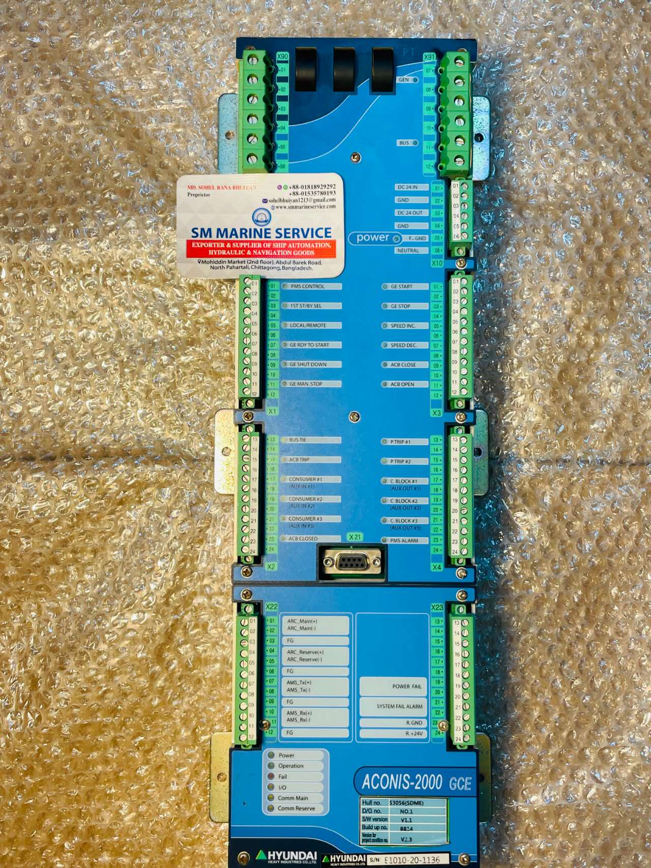
The GCE shown here is an actual SM MARINE SERVICE™ stock unit.
Manufacturer / System Brand: Hyundai
System: ACONIS-2000® Power Management System
Equipment: GCE – Generator Control Equipment
Product Type: Marine Generator / PMS Control Equipment
Control Supply: 24VDC
Application: Shipboard generator automation and power management
The photographed unit also shows:
SW Version: V1.1
Build-up No.: B814
Software/Program reference: V2.3
These software/build references are particularly important when sourcing a replacement GCE because configuration and project-specific programming should be checked before installation.
The GCE is effectively the generator-side control equipment of the ACONIS-2000 PMS.
Hyundai documentation states that the GCE is mounted inside each generator panel and directly receives I/O signals from the:
Bus Bar
Generator
Engine
Circuit Breaker
The individual GCE units communicate with one another through a redundant field-bus based on ARC-net.
This distributed arrangement means each generator has its own control hardware rather than relying only on one centralized generator controller.
The ACONIS-2000 PMS supports a wide range of automatic generator-management functions.
Documented functions include:
These functions depend on the vessel's installed hardware, software and configured PMS logic.
The photographed GCE has dedicated I/O markings for:
GE START
GE STOP
as well as:
GE READY TO START
GE SHUT DOWN
GE MAN. STOP
This illustrates the GCE's direct interface with the generator engine and its associated starting/stopping logic.
The unit also provides clearly marked:
SPEED INC.
and
SPEED DEC.
control signals.
These outputs are used within the generator-control sequence to adjust engine/governor speed as required for frequency control and synchronization.
Dedicated connections visible on the unit include:
ACB CLOSE
ACB OPEN
ACB CLOSED
ACB TRIP
The Air Circuit Breaker is a critical part of the generator's connection to the ship's main busbar.
The GCE therefore participates directly in generator-breaker control and status monitoring.
Before an incoming generator can be connected to an energized busbar, its electrical conditions must be suitable for synchronization.
The ACONIS PMS manages synchronization as part of its automatic generator-control logic.
It coordinates the generator control process and ACB closing sequence according to the configured PMS parameters.
Once multiple generators are connected to the busbar, the PMS can perform load sharing.
This prevents one generator from carrying an excessive portion of the vessel's electrical demand while another generator remains lightly loaded.
Load sharing is one of the documented automatic-mode functions of ACONIS-2000.
The PMS can automatically determine when additional generating capacity is needed.
When vessel electrical demand rises, another standby generator can be started and connected.
When demand falls sufficiently, the PMS can unload and stop unnecessary generating capacity according to its configured logic.
This is referred to as:
Load Dependent Start / Stop.
One of the most important functions of a marine PMS is blackout recovery.
The ACONIS-2000 documentation specifically includes:
Stand-by start and ACB close at Black-Out
within automatic-mode functionality.
A correctly functioning GCE is therefore important to the vessel's generator recovery sequence.
The photographed GCE includes connections marked:
P TRIP #1
P TRIP #2
The ACONIS system supports preferential-trip logic, which can be used to disconnect selected non-essential loads when generator capacity or operating conditions require load reduction.
Visible terminals also include:
CONSUMER #1
CONSUMER #2
CONSUMER #3
and:
C BLOCK #1
C BLOCK #2
C BLOCK #3
ACONIS-2000 documentation includes heavy consumer start and accept functionality.
This is important aboard vessels where large consumers such as pumps, thrusters or other high-load machinery can cause a sudden electrical-load increase.
Visible inputs include:
PMS CONTROL
1ST ST/BY SEL
LOCAL/REMOTE
These signals form part of the operational selection logic.
The system documentation describes Auto, Manual and Local operating arrangements, with automatic PMS functions available according to the selected operating state.
The GCE units communicate over a redundant field bus based on the ARC-net standard.
The photographed hardware provides visible communication references:
ARC_Main (+/-)
ARC_Reserve (+/-)
as well as status LEDs for:
Comm Main
and
Comm Reserve.
This redundancy helps maintain generator-to-generator PMS communication if one communication path develops a problem.
The lower section of the photographed unit includes LEDs marked:
Power
Operation
Fail
I/O
Comm Main
Comm Reserve
These indicators are useful during fault diagnosis because they provide an immediate indication of controller power, operating condition, I/O status and communication state.
Available ACONIS-2000 PMS documentation gives the following general GCE/system specifications:
Control Power Supply: 24VDC
Processor: Intel XScale PXA-255
Processor Clock: 200 MHz
SDRAM: 32 MB
Read/Write Program Memory: 32 MB
Non-volatile Memory: 4 KB
Watchdog / Power-Fail Logic: Yes
Documented Operating Temperature: 0°C to 70°C.
These are documented system specifications and should not be used to assume that every project-specific GCE software build is directly interchangeable.
ACONIS documentation explains that each GCE requires generator identification.
A documented configuration uses:
0 = Generator #1
1 = Generator #2
2 = Generator #3
3 = Generator #4.
The ACONIS-2000 system documentation covers control of up to four diesel generator sets in the referenced configuration.
This distinction is important when requesting a spare.
Installed inside the generator panel.
It handles generator I/O, control logic, breaker signals, PMS communication and related generator-management functions.
Installed flush-mounted on the generator section of the switchboard.
It provides operator displays, LEDs, pushbuttons and access to PMS configuration/parameter functions.
Therefore:
GCE ≠ GDP
A buyer asking for an “ACONIS controller” should confirm which unit is actually required.
The GCMI-CPU is another important search term associated with the GCE.
ACONIS documentation specifically shows the GCE and GCMI-CPU together in the hardware section.
Therefore buyers may search for:
ACONIS GCMI CPU
Hyundai GCMI-CPU
GCE CPU Board
ACONIS CPU Module
These terms should not automatically be treated as meaning a complete GCE assembly; the requested hardware must be confirmed from photographs and part information.
Check the 24VDC control supply, input terminals, fuse/protection circuit and wiring before replacing the controller.
Check controller status LEDs, system-fail condition, software/configuration and communication status.
Inspect the ARC_Main wiring, connectors, termination and neighboring GCE communication.
Because the system uses redundant communication, also compare Comm Main with Comm Reserve.
Inspect the reserve ARC-net path independently rather than assuming a processor failure.
The photographed GCE includes a dedicated SYSTEM FAIL ALARM output.
Check power, watchdog/controller state, communications and internal status before deciding that the complete unit is defective.
Check:
PMS control mode, Local/Remote status, standby selection, GE Ready to Start input, generator alarm/interlock condition and start output.
Check synchronization conditions, ACB status/interlocks, ACB Close output, breaker feedback and configured PMS parameters.
Check generator kW feedback, governor speed-control signals, communication between GCE units and load-sharing configuration.
Do not simply increase protection limits.
Check actual generator load direction, CT/power measurement, governor response and protection parameters. The ACONIS system includes reverse-power protection as a documented function.
This is particularly important for ACONIS-2000.
Before replacing a GCE, confirm:
ACONIS system version
GCE hardware/version
SW version
Build number
Generator number / GCE ID
Vessel/project configuration
I/O configuration
Communication arrangement
A physically identical ACONIS GCE should not automatically be assumed to be a plug-and-play replacement for every vessel.
Project software and parameter configuration can matter.
SM MARINE SERVICE™ supports sourcing and supply of Hyundai ACONIS-2000 Power Management System equipment and marine generator-control spare parts.
Typical requirements can include:
ACONIS-2000 GCE Generator Control Equipment
GCE Complete Unit
GDP Generator Display Panel
GCMI-CPU
GCE CPU / Control Electronics
ACONIS PMS Modules
Generator Control & Interface Components
Communication Components
Replacement GCE Assemblies
For replacement enquiries, providing clear photographs of the original unit, software/build information and vessel generator configuration helps reduce compatibility errors.
You can also visit the SM MARINE SERVICE™ website for marine automation, generator control and power-management equipment.
Many existing vessels were built around the ACONIS-2000 PMS architecture.
Replacing the entire PMS may involve changes to generator controls, switchboard wiring, protection logic, communication networks and operating interfaces.
For that reason, maintaining an existing system with correctly matched GCE, GDP, CPU and associated spare parts can remain a practical solution for vessels where the original system is otherwise serviceable.
GCE means Generator Control Equipment.
The GCE is mounted inside each generator panel.
It is a computer-based marine Power Management System designed for generator/power-plant automation.
The documented control power supply is 24VDC.
Yes. Load sharing is a documented automatic-mode function.
Yes. Blackout recovery/standby-generator start and breaker closing are documented PMS functions.
Yes. Generator/breaker I/O is directly connected to the GCE, and the photographed unit includes ACB Close/Open/Trip-related connections.
The GCE-to-GCE redundant field bus is based on ARC-net.
No. GCE is the Generator Control Equipment inside the generator panel; GDP is the Generator Display Panel mounted at the switchboard generator section.
Not safely based on appearance alone. Software/build, generator ID, project configuration and I/O parameters should be verified before replacement.
Subject to stock, SM MARINE SERVICE™ can support new, used, refurbished or reconditioned marine automation and generator-control equipment.
Hyundai ACONIS-2000 GCE Generator Control Equipment is the generator-side control module of the ACONIS-2000 Marine Power Management System. Installed inside each generator panel, the GCE interfaces with generator, engine, busbar and ACB signals and communicates with other GCE units through a redundant ARC-net field bus. The ACONIS-2000 PMS supports generator auto start/stop, synchronization, ACB control, load sharing, frequency/load control, blackout recovery, reverse-power protection, preferential trip, heavy-consumer logic and generator alarm monitoring. The photographed SM MARINE SERVICE™ unit is marked ACONIS-2000 GCE, SW Version V1.1, Build-up No. B814 and V2.3. Replacement should be matched by hardware, software/build and vessel configuration.
SM MARINE SERVICE™
Marine Automation & Navigation Equipment Supplier
Available Condition:
• New Equipment • Used Equipment • Refurbished Equipment • Reconditioned Equipment
Stock Location:
• Bangladesh • China
Services:
• Worldwide Shipping • Technical Support • Spare Parts Supply • Marine Equipment Sourcing
Contact Information
SM MARINE SERVICE™ Samir Market, DT Road, Pahartali, beside CDA Market, Chattogram, Bangladesh
Mobile / WhatsApp / Viber: +88 01818 929292
Email: info@smmarineservice.com
Website: www.smmarineservice.com
0

BDT 0

BDT 0

BDT 0

BDT 0
Marine Equipment Supplier