BOLLFILTER Protection Systems Electronic Control Box / Control Panel
BOLL & KIRCH Filterbau GmbH / BOLLFILTER
New product
Manufacturer: BOLL & KIRCH Filterbau GmbH / BOLLFILTER
Country of Origin: Germany
Product Type: Electronic Control Box / Control Panel for Automatic Backflushing Filter Systems
Marine Application: Fuel oil, lube oil, hydraulic oil, and process-water automatic filtration systems installed on ships and offshore vessels
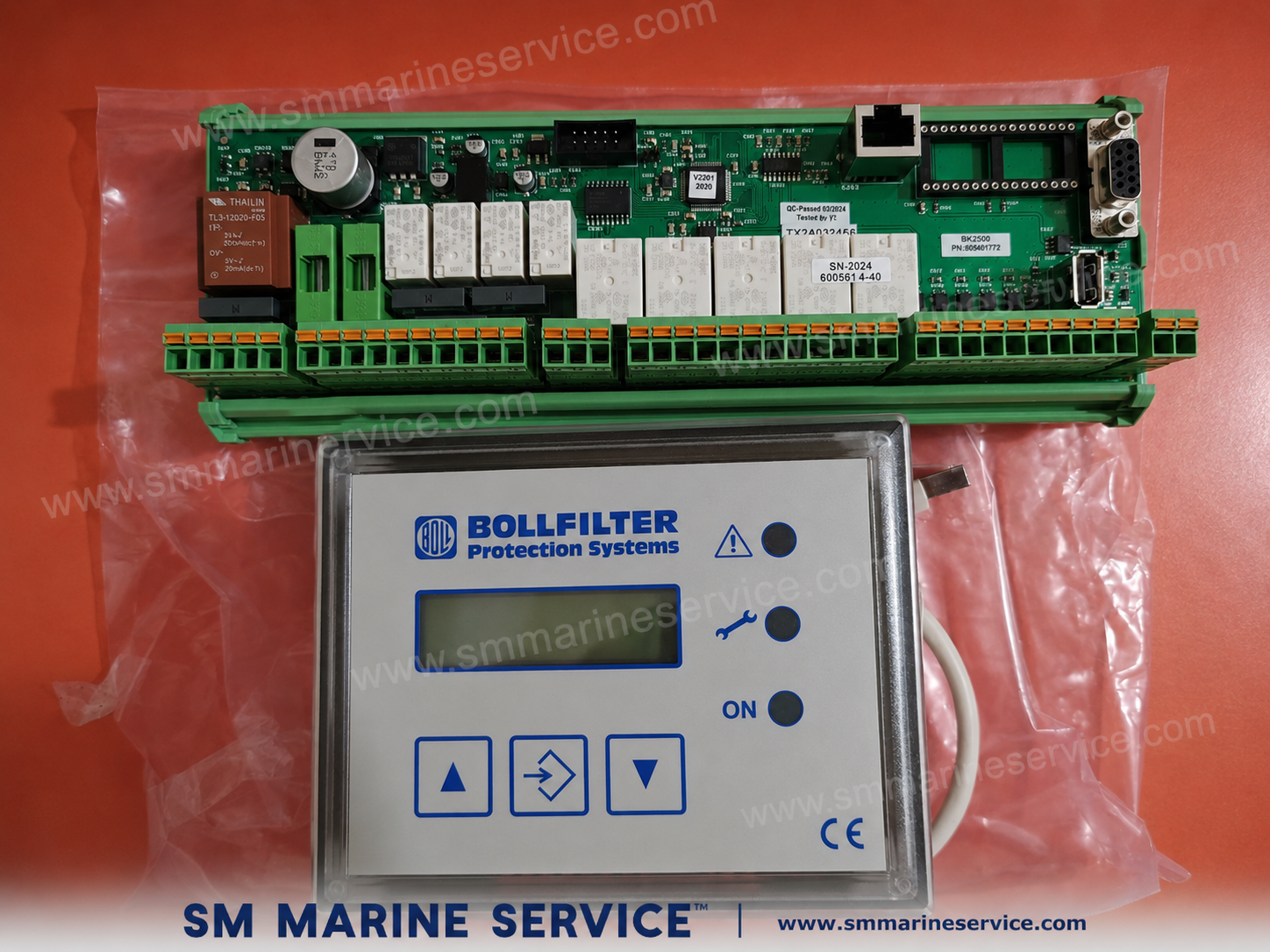
The equipment shown in the image is a BOLLFILTER Protection Systems electronic control unit with operator display panel, used on BOLL automatic marine filtration systems. In marine engine rooms, these control boxes are installed to supervise and automate the operation of self-cleaning / backflushing filters that protect main engines, diesel generators, fuel treatment systems, lube oil systems, hydraulic circuits, and other critical machinery.
BOLL & KIRCH is one of the best-known names in industrial and marine filtration. Its automatic filters are widely used where continuous filtration is essential and where manual filter cleaning would create operational risk, manpower burden, or downtime. The electronic control box is the “brain” of the system: it monitors differential pressure or contamination condition, initiates backflushing sequences, displays alarms and status messages, and helps engineers keep the filter operating without interrupting flow to the protected machinery.
For marine engineers and technical purchasers, this is not just a small control panel—it is a mission-critical automation component. A failure in the control box can stop automatic cleaning, cause excessive differential pressure, increase contamination risk, and ultimately threaten engines, pumps, injection equipment, separators, coolers, or hydraulic components downstream.


The BOLLFILTER Protection Systems control box is an electronic controller for automatic backflushing filters. It is designed to operate with selected BOLL automatic filter systems used in marine and industrial service. Depending on filter type and controller generation, the control box can manage functions such as:
In practical shipboard use, the control box sits between the filter mechanical assembly and the ship’s automation/electrical system. It ensures that when contamination in the filter rises to a preset level, the filter is cleaned automatically without shutting down the fuel, lubricating oil, or water flow.
BOLL documentation for its electronic control boxes describes these units as part of the automatic filter package and highlights their role in safe installation, operation, fault indication, and maintenance support. BOLLFILTER’s service documentation also shows controller families such as Type 2200, 2300, and 2310 used for automatic filter control in different system configurations.
From an engine-room operations perspective, this means the controller helps the vessel maintain continuous filtration with minimal manual intervention, which is especially important on unmanned machinery spaces, long voyages, heavy-fuel service, and ships with high reliability requirements.
Although exact functions vary by filter model and controller type, the BOLLFILTER control box generally provides the following practical features:
The controller automatically initiates the cleaning sequence when contamination reaches a defined threshold or when the programmed logic demands a flush cycle. This reduces manual work and keeps filtration performance stable.
The front display panel allows engineers to view operating status, menu items, fault messages, counters, or configuration parameters. This is important for quick onboard diagnostics.
The up/down/enter style buttons allow the operator to access settings, acknowledge messages, review information, and navigate service menus.
Typical front LEDs or status indicators show:
The PCB contains relays and electronic I/O used to switch actuators, solenoid valves, alarms, and related control outputs associated with the filter’s cleaning process.
Automatic marine filters rely on pressure differential or contamination condition to decide when cleaning is required. The controller processes these inputs and triggers the proper response.
BOLL’s control box manuals include troubleshooting and safety guidance because controller failure, wrong installation, or improper wiring can prevent correct filter operation. That makes proper commissioning and maintenance essential.
On vessels where machinery must run for long periods without stopping, automatic filters plus electronic control significantly improve operational continuity compared with purely manual filter arrangements.
The product photo shows two major assemblies: the front operator panel and the main electronic control PCB. Depending on controller type, the internal arrangement may vary, but the principal components usually include the following.
This is the visible operator interface mounted on the control box door or panel front. It typically includes:
The PCB is the heart of the unit. It may contain:
These are used for connection of:
The control box includes internal power conditioning and supply components to energize the controller electronics and associated switching circuits.
Relays on the PCB are used to command the filter’s automatic flushing sequence, alarm outputs, and interlocks.
Some versions include communication or service ports for programming, diagnostics, or integration with external monitoring systems.
In the complete BOLLFILTER control cabinet, the electronics are housed inside a robust enclosure designed for engine-room installation. This protects the electronics from accidental contact, dust, vibration, and general marine service conditions.
For ship managers and spare-parts buyers, the most commonly requested items are often not only the full control box but also:
This is why SM MARINE SERVICE™ recommends identifying the controller type, filter type, serial number, and PCB part marking before ordering replacement parts.
BOLLFILTER automatic filtration systems are used in several marine services. The control box can therefore appear in different areas of the vessel depending on the filter package installed.
Used to protect:
Installed to protect:
Used where sensitive hydraulic equipment must be protected from contamination, including deck machinery or process equipment.
Some BOLL automatic filters are used for water filtration duties, where the controller manages the automatic cleaning cycle to keep flow stable.
The same BOLL control concept is also seen on offshore support vessels, industrial skids, power modules, and plant installations where BOLL automatic filters are fitted.
In all of these cases, the control box plays the same essential role: it keeps the filter self-cleaning and operational so the protected machinery receives clean fluid continuously.


The BOLLFILTER Protection Systems control panel is commonly associated with the following marine applications:
For marine operators, the main value of the system is that it allows filtration and cleaning to occur without frequent manual dismantling of filter elements, helping reduce downtime and protecting critical downstream equipment.
Like any marine automation component, the BOLLFILTER control box can develop faults due to age, vibration, humidity, power instability, dirty connections, or component failure. Below are the most common field problems seen on automatic filter controllers.
If the display is dead but power is present, the fault may be on the main PCB power supply section or HMI/display board.
Many “controller faults” are actually field-device faults such as stuck solenoid valves, failed pressure switches, or disconnected wiring.
If alarms return immediately after a flush, the root cause may be mechanical contamination or ineffective cleaning, not only the control box itself.
Depending on filter type and controller version, engineers may see conditions such as:
Exact wording differs by controller version and filter system, so the correct operating manual for the exact control box type should always be used before troubleshooting onboard.
The control box itself is only one part of the total BOLLFILTER system. Reliable operation depends on both electronic maintenance and mechanical filter maintenance.
Marine humidity, salt-laden air, and oil mist can damage electronics over time. During planned maintenance, inspect the cabinet interior for:
Vibration can loosen connections. Loose terminals cause intermittent faults, overheating, and nuisance alarms.
Older control boards often fail due to:
A weak or non-responsive keypad can make troubleshooting difficult during emergencies. Test HMI function during routine inspections.
Voltage fluctuation, wrong supply voltage, or poor grounding can damage the controller. Verify the power supply matches the controller rating.
A heavily fouled filter will trigger frequent flush commands and alarms, increasing wear on the control system and associated valves.
If the flushing path is blocked, the controller may command cleaning but contamination will remain high.
A faulty pressure switch or differential pressure transmitter can cause false alarms or prevent automatic flushing.
Backflush performance depends on proper movement of valves and actuators.
A sudden increase in flush count often indicates worsening contamination, damaged filter candles, or changing fuel/oil quality.
For this reason, SM MARINE SERVICE™ always recommends inspecting the complete filter package—not only the electronic board—when a BOLLFILTER control problem is reported.
Despite the growth of modern integrated automation systems, BOLLFILTER automatic filter control boxes remain widely used because they solve a very practical shipboard problem: continuous filtration without constant manual cleaning.
Ships still rely on this equipment because it offers:
Clean fuel and lubricating oil are essential for injectors, pumps, bearings, governors, separators, and engines.
Instead of repeatedly opening filters for cleaning, the automatic filter and its controller manage the process during operation.
A properly working automatic filter can continue protecting the system even during long voyages, variable fuel conditions, and unmanned machinery periods.
BOLL automatic filters have been used for many years across marine and industrial sectors. Their control systems are familiar to ship staff, service engineers, and technical managers.
Even older control boxes are often worth repairing because the associated BOLL filter systems remain in service for long periods. Replacement PCBs, HMIs, relays, and refurbished control units are therefore still in demand.
Its main function is to monitor and control the automatic cleaning / backflushing operation of a BOLL automatic filter and to provide alarm and operating status information.
No. Depending on the filter model, it can be used on fuel oil, lube oil, hydraulic oil, process water, and other automatic marine filtration systems.
Yes. The HMI/display panel, keypad membrane, and main control PCB can fail separately, so correct diagnosis is important before ordering spare parts.
Ideally provide:
In many cases, yes. Common repairs include:
The filter may stop automatic cleaning, go into alarm, or require manual intervention. If contamination increases without proper flushing, downstream machinery protection can be compromised.
No. BOLL has used different controller types across different filter models and periods. Always match the controller with the specific filter system and documentation.
Yes. SM MARINE SERVICE™ can support sourcing of new, used, refurbished, or reconditioned BOLLFILTER control units, display panels, PCBs, and related marine automation spare parts, subject to stock and identification details.
The BOLLFILTER Protection Systems Electronic Control Box / Control Panel is a marine automatic filter controller manufactured by BOLL & KIRCH, Germany. It is used to supervise and automate the operation of BOLL self-cleaning / backflushing filters installed in fuel oil, lubricating oil, hydraulic oil, and water filtration systems onboard ships. The controller typically includes a display panel, keypad, alarm indication, relay outputs, and a main PCB for managing automatic flush cycles, monitoring filter condition, and interfacing with shipboard alarm systems. It is an important spare part for maintaining reliable automatic filtration and machinery protection in marine engine-room operations.
Below are useful BOLLFILTER / BOLL & KIRCH technical references relevant to electronic control boxes and automatic filter systems. Because BOLL uses different controller generations and filter types, always confirm the exact controller type and filter model before using a manual for onboard work.
Marine Automation & Navigation Equipment Supplier
Available Condition:
• New Equipment • Used Equipment • Refurbished Equipment • Reconditioned Equipment
Stock Location:
• Bangladesh • China
Services:
• Worldwide Shipping • Technical Support • Spare Parts Supply • Marine Equipment Sourcing
SM MARINE SERVICE™
Samir Market, DT Road, Pahartali, beside CDA Market, Chattogram, Bangladesh
Mobile / WhatsApp / Viber: +88 01818 929292
Email: info@smmarineservice.com
Website: www.smmarineservice.com
0
BDT 0
BDT 0
BDT 0
BDT 0
Marine Equipment Supplier